


Telemonitor For Recording Phone Calls
#telemonitor
#phone
#recording
#tape recorder
#transistor
#switch
#on-hook
#telecommunication
#audio
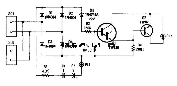
Description: This circuit controls a tape recorder through PL2. When the phone is on-hook, D5 conducts, activating Q1 and disabling Q2. Additionally, ringing voltage will also trigger D5 to conduct; C2 and C1 should be rated for 150 V or higher. When the phone is off-hook, the approximately 10 V present on the line does not cause D5 to break down, keeping Q1 off and allowing Q2 to be biased on. PL2 connects to the remote control jack of the tape recorder, while audio is sourced from PL1. Caution: It is advisable to use either a battery-operated tape recorder or a tape recorder powered by an FCC/CSA/UL-approved AC adapter to prevent the risk of inadvertently applying 120 Vac to the telephone line.
This circuit serves as a remote control interface for tape recorders, utilizing a switching mechanism that responds to the state of a telephone line. The diode D5 plays a critical role in the circuit's operation by allowing current to flow when the phone is on-hook, which in turn activates transistor Q1. This activation effectively disables transistor Q2, ensuring that the tape recorder remains in standby mode until the phone is taken off-hook.
The inclusion of capacitors C1 and C2, rated at 150 V or higher, is essential for handling potential ringing voltage that may occur on the telephone line. This design choice ensures that the circuit can withstand voltage spikes without damaging sensitive components. When the phone is off-hook, the voltage present on the line is not sufficient to break down D5, allowing Q1 to remain off and ensuring that Q2 is biased on, which is necessary for the operation of the tape recorder.
PL2 serves as the connection point for the remote control jack of the tape recorder, facilitating audio input from PL1. The design emphasizes safety by recommending the use of battery-operated tape recorders or those powered by approved AC adapters. This precaution is crucial to prevent any accidental exposure of the telephone line to 120 Vac, which could pose safety hazards and damage the circuit. Overall, this circuit provides a reliable method for controlling tape recorders in conjunction with telephone line activity, ensuring both functionality and safety. This circuit switches a tape recorder via PL2. When on-hook, D5 conducts, turns on Ql, and cuts off Q 2. Ringing voltage will also cause D5 to conduct; C2 and CI should be rated 150 V or higher. When phone is off-hook, the 10 V or so present on the line will not break down D5, and therefore Ql is off and Q2 is biased on. PL2 connects to the remote control jack on the tape recorder. Audio is taken from PL1. Caution: Use either a battery tape recorder or an FCC/CSA/UL-approved ac adapter-powered tape recorder.
This precaution is to avoid inadvertent 120 Vac on the telephone line.
This circuit serves as a remote control interface for tape recorders, utilizing a switching mechanism that responds to the state of a telephone line. The diode D5 plays a critical role in the circuit's operation by allowing current to flow when the phone is on-hook, which in turn activates transistor Q1. This activation effectively disables transistor Q2, ensuring that the tape recorder remains in standby mode until the phone is taken off-hook.
The inclusion of capacitors C1 and C2, rated at 150 V or higher, is essential for handling potential ringing voltage that may occur on the telephone line. This design choice ensures that the circuit can withstand voltage spikes without damaging sensitive components. When the phone is off-hook, the voltage present on the line is not sufficient to break down D5, allowing Q1 to remain off and ensuring that Q2 is biased on, which is necessary for the operation of the tape recorder.
PL2 serves as the connection point for the remote control jack of the tape recorder, facilitating audio input from PL1. The design emphasizes safety by recommending the use of battery-operated tape recorders or those powered by approved AC adapters. This precaution is crucial to prevent any accidental exposure of the telephone line to 120 Vac, which could pose safety hazards and damage the circuit. Overall, this circuit provides a reliable method for controlling tape recorders in conjunction with telephone line activity, ensuring both functionality and safety. This circuit switches a tape recorder via PL2. When on-hook, D5 conducts, turns on Ql, and cuts off Q 2. Ringing voltage will also cause D5 to conduct; C2 and CI should be rated 150 V or higher. When phone is off-hook, the 10 V or so present on the line will not break down D5, and therefore Ql is off and Q2 is biased on. PL2 connects to the remote control jack on the tape recorder. Audio is taken from PL1. Caution: Use either a battery tape recorder or an FCC/CSA/UL-approved ac adapter-powered tape recorder.
This precaution is to avoid inadvertent 120 Vac on the telephone line.
Acoustic Field Generator Circuit
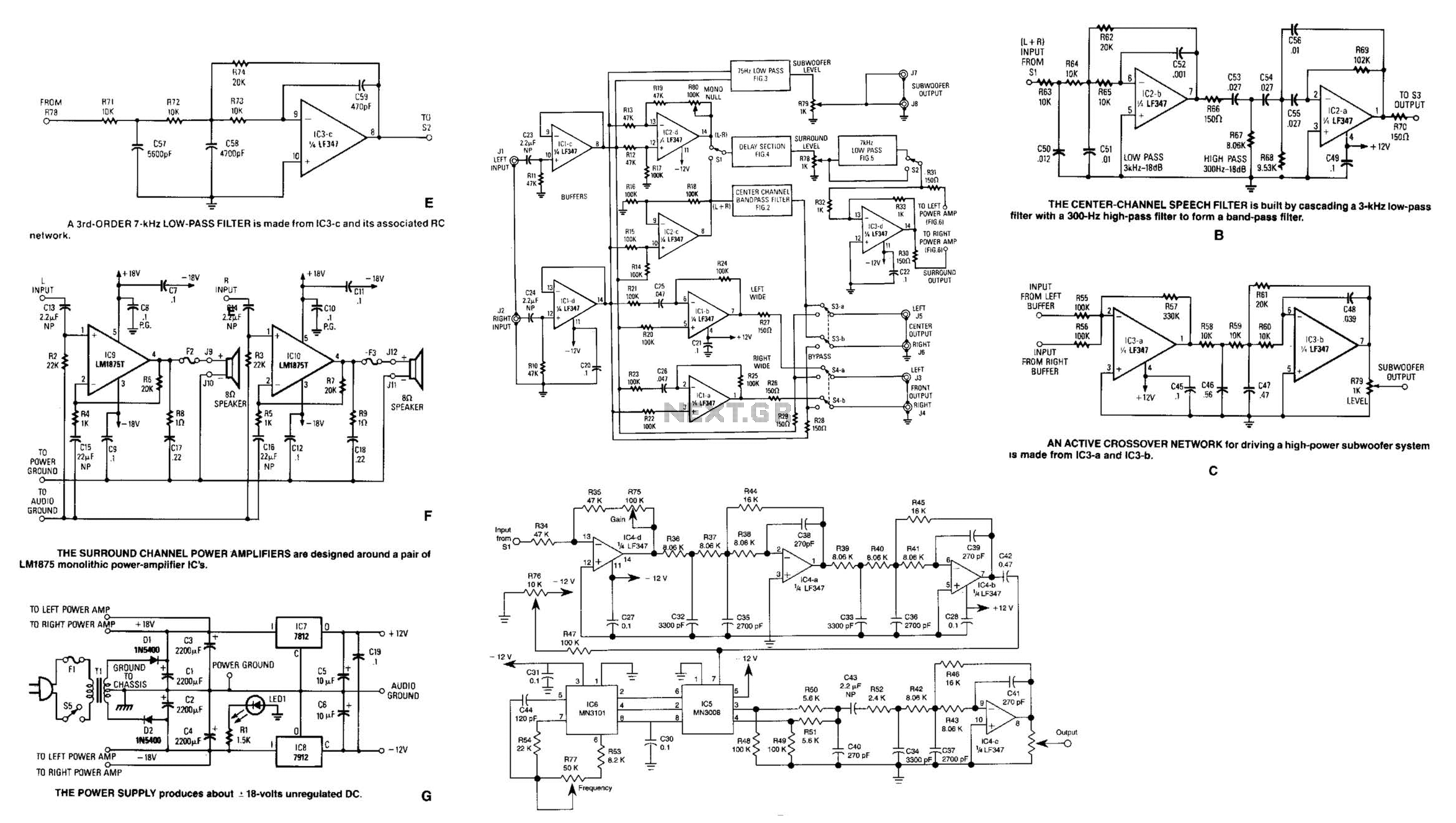
Referring to the simplified schematic in A, the audio frequency generator (AFG) consists of 10 relatively simple circuit elements. IC1-c and IC1-d are configured as unity-gain non-inverting buffer amplifiers. The summing amplifier, IC2-c, combines equal amounts of the left and...
Length 1 minute delay relay pull transistor circuit diagram
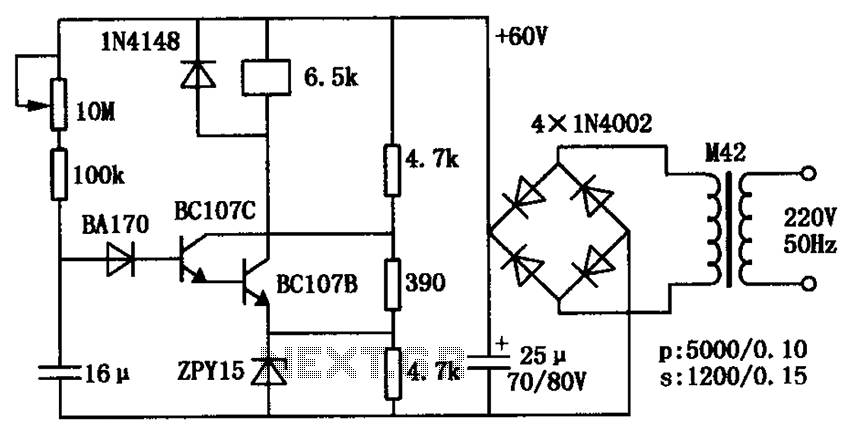
The circuit consists of a transistor relay delay pull mechanism. Initially, with a 16 µF capacitor at zero voltage, both transistors are off, and the relay remains inactive. As the 16 µF capacitor charges over time, the voltage increases to...
help me identify this amp
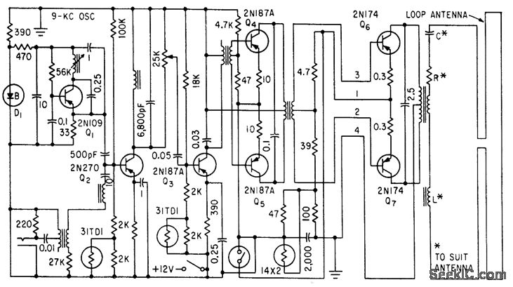
A long-time observer has acquired four vintage amplifiers for their enclosures, but with limited knowledge of older equipment, they have not made much progress.
The project involves the restoration and utilization of vintage amplifiers, which typically feature discrete component designs and...
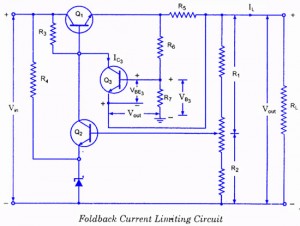
Controlled Transistor Series Regulator With Overload and Short-Circuit Protection
If the load resistance (RL) is reduced or the load terminals are accidentally shorted, a very large load current will flow, potentially damaging the pass transistor (Q1), diode, or other components. Fuse protection may not be sufficient, as the transistor...
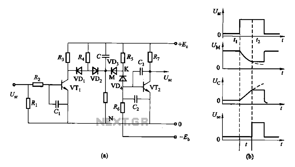
As of control rechargeable delay circuit
This is a control rechargeable delay circuit. Under normal circumstances, when there is no input signal, the transistor VTi is off. VTz is conducting, resulting in a low output potential (U). When a signal is applied, VTi turns on, VTz...
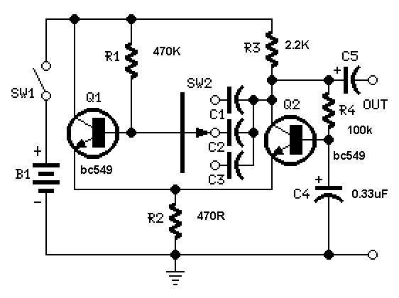
Simple Square wave Generator using transistors ~ Easy Electronics
A useful feature of this circuit is that the frequency can be changed by modifying the capacitor value. A switch can be added to select between various frequencies.
This circuit utilizes a capacitor in conjunction with an oscillator to determine its...
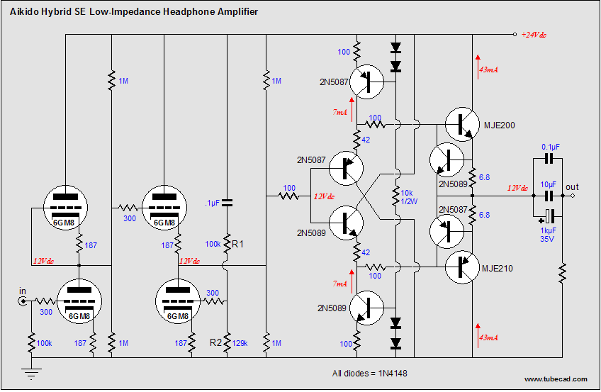
Aikido octal mono PCBs and 5687 PCBs and Aikido and 300B amplifiers
Buffers are a specific category of amplifiers, and power buffers are a subset of power amplifiers. The defining characteristics of all buffers include unity gain and a low impedance output, ideally accompanied by low distortion. When examining commercially available buffers,...
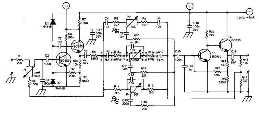
Universal Audio Line Amplifier
A line amplifier is a valuable component for matching line signals or increasing their levels. This functionality is essential during recording sessions or in public-address systems. Additionally, multiple line amplifiers can be combined to create a line mixer. The amplifier's...
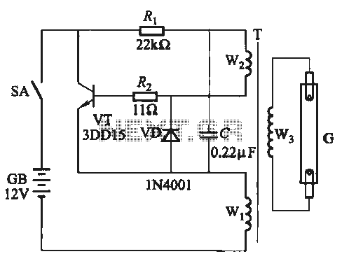
A five inverter circuit
A self-excited transistor inverter circuit is designed for improved performance and features a relatively simple schematic. It is suitable for driving fluorescent lamps with a power rating between 8 to 40 watts. This inverter can operate stably even when the...