


Telephone Ringer
#telephone
#ringer
#audio
#tone generator
#timing circuit
#electronics
#communication
#sound generation

Description: This circuit generates the sound of the electronic ringer found in modern telephones, replacing the two-bell electromechanical ringers used previously. The ringing pattern adheres to the United States standard of 2 seconds on and 4 seconds off. During the "on" interval, the tone alternates between two selectable frequencies at a rate of 20Hz. The NAND Schmitt trigger U1A is configured as a relaxation oscillator, adjusted with RV1 for a 40Hz waveform at test point TP1. This waveform is divided by flip-flop U2A to provide a 20Hz, 50-percent duty cycle square wave at U2A's Q output, along with a complementary square wave at U2A's Q-not output. When U2A's Q output is high, the relaxation oscillator formed by U1B is enabled. Conversely, when U2A's Q-not output is high, the relaxation oscillator formed by U1C is enabled. NAND gate U1D performs an OR function for the two oscillator outputs and drives flip-flop U2B, which divides the waveform by two to ensure a 50 percent duty cycle. The resulting waveform at U2B's Q output is a square wave that alternates between two audible frequencies at a 20Hz rate. The pitch of these frequencies is individually adjustable from approximately 500Hz to 2500Hz using RV2 and RV3, allowing for selection of a suitable sound output. A frequency divider chain consisting of U4, U5, and U6 is driven from the 20Hz waveform at U2A's Q-not output. U4 and U5 provide a frequency division of 40, resulting in a 0.5Hz square wave at U5B pin 13. This square wave drives U6, which is configured as a divide-by-3. U6's "0" output generates a 0.167Hz waveform that is high for 2 seconds and low for 4 seconds. Paralleled gates U3A and D, driven by U2B's Q output, drive one side of the piezo audible transducer, as well as the inputs of two additional paralleled gates, U3B and C. The outputs of U3B and C drive the other side of the transducer. All four of U3's NAND gates are enabled by U6's "0" output, resulting in a tone pattern of 2 seconds on and 4 seconds off. U3's bridge configuration doubles the voltage across the transducer, producing ample volume. If desired, the piezo transducer may be replaced with a 100-ohm-impedance dynamic loudspeaker. The power supply voltage is not critical and can vary between 6 and 12 volts. However, it should be regulated to prevent frequency variations in the circuit's oscillators. The three frequency-selection capacitors should be stable polyester-film types, and the 0.1uF decoupling capacitors should be X7R-ceramic types. The 1N4001 rectifier protects the circuit from power supply polarity reversal. Layout is not critical; however, the 0.1uF decoupling capacitors should be placed as close as possible to their respective ICs.
This electronic ringer circuit represents a modern solution for generating ringing tones in telecommunication devices. The use of a NAND Schmitt trigger as a relaxation oscillator allows for precise control over the frequency output, which is critical for achieving the desired sound characteristics. The circuit's design incorporates multiple oscillators and frequency dividers to create a complex but reliable waveform that adheres to standard ringing patterns.
The flexibility provided by adjustable frequency settings allows for customization, catering to different user preferences or applications. The choice of components, such as stable polyester-film capacitors for frequency selection and X7R-ceramic types for decoupling, ensures that the circuit maintains performance under varying conditions. The inclusion of a rectifier also enhances reliability by safeguarding against incorrect power supply connections.
Overall, the circuit's architecture, including the bridge configuration of the NAND gates, maximizes output volume, making it suitable for various applications, including telephones and alarms. This design exemplifies the integration of digital logic and analog components to achieve a functional, user-friendly electronic ringer system.This circuit generates the sound of the electronic ringer found in modern telephones, supplanting the 2-bell electromechanical ringers used previously. The ringing pattern follows the United States convention of 2 seconds on, and 4 seconds off. During the "on" interval, the tone alternates between two selectable frequencies at a rate of 20Hz. Refe ring to the schematic, NAND Schmitt trigger U1A is configured as a relaxation oscillator, adjusted with RV1 for a 40Hz waveform at test point TP1. This waveform is divided by flip-flop U2A to provide a 20 Hz, 50-percent duty cycle square wave at U2A`s Q output, and a complimentary square wave at U2A`s Q-not output.
When U2A`s Q output is high, the relaxation oscillator formed by U1B is enabled. When U2A`s Q-not output is high, the relaxation oscillator formed by U1C is enabled. NAND gate U1D provides an OR function for the two oscillator outputs, and drives flip-flop U2B, which divides the waveform by two to ensure a 50 per-cent duty cycle. The resulting waveform at U2B`s Q output is a square-wave that alternates between two audible frequencies at a 20Hz rate.
The pitch of these frequencies are individually adjustable from approximately 500Hz to 2500Hz with RV2 and RV3, and may be selected for a suitable sound output. A frequency divider chain consisting of U4, U5 and U6 is driven from the 20Hz waveform at U2A`s Q-not output.
U4 and U5 provide a frequency division of 40, resulting in a 0. 5Hz square wave at U5B pin 13. This square wave drives U6, which is configured as a divide-by-3. U6`s "0" output is a 0. 167Hz waveform which is at a high state for 2 seconds, and a low state for 4 seconds. Paralleled gates U3A and D, driven by U2B`s Q output, drive one side of the piezo audible transducer, as well as the inputs of two additional paralleled gates, U3B and C. U3B and C`s outputs drive the other side of the transducer. All four of U3`s NAND gates are enabled by U6`s "0" output, resulting in a 2-second-on, 4-second-off tone pattern.
U3`s bridge configuration doubles the voltage that appears across the transducer, producing ample volume. If desired, the piezo transducer may be substituted with a 100-ohm-impedance dynamic loudspeaker. The power supply voltage is not critical and may vary between 6 and 12 volts. However, it should be regulated to prevent frequency variations in the circuit`s oscillators. The three frequency-selection capacitors should be stable polyester-film types, and the 0. 1uF decoupling capacitors should be X7R-ceramic types. The 1N4001 rectifier protects the circuit from power supply polarity reversal. Layout is not critical, however, the 0. 1uF decoupling capacitors should be located as close as possible to their respective ICs.
This electronic ringer circuit represents a modern solution for generating ringing tones in telecommunication devices. The use of a NAND Schmitt trigger as a relaxation oscillator allows for precise control over the frequency output, which is critical for achieving the desired sound characteristics. The circuit's design incorporates multiple oscillators and frequency dividers to create a complex but reliable waveform that adheres to standard ringing patterns.
The flexibility provided by adjustable frequency settings allows for customization, catering to different user preferences or applications. The choice of components, such as stable polyester-film capacitors for frequency selection and X7R-ceramic types for decoupling, ensures that the circuit maintains performance under varying conditions. The inclusion of a rectifier also enhances reliability by safeguarding against incorrect power supply connections.
Overall, the circuit's architecture, including the bridge configuration of the NAND gates, maximizes output volume, making it suitable for various applications, including telephones and alarms. This design exemplifies the integration of digital logic and analog components to achieve a functional, user-friendly electronic ringer system.This circuit generates the sound of the electronic ringer found in modern telephones, supplanting the 2-bell electromechanical ringers used previously. The ringing pattern follows the United States convention of 2 seconds on, and 4 seconds off. During the "on" interval, the tone alternates between two selectable frequencies at a rate of 20Hz. Refe ring to the schematic, NAND Schmitt trigger U1A is configured as a relaxation oscillator, adjusted with RV1 for a 40Hz waveform at test point TP1. This waveform is divided by flip-flop U2A to provide a 20 Hz, 50-percent duty cycle square wave at U2A`s Q output, and a complimentary square wave at U2A`s Q-not output.
When U2A`s Q output is high, the relaxation oscillator formed by U1B is enabled. When U2A`s Q-not output is high, the relaxation oscillator formed by U1C is enabled. NAND gate U1D provides an OR function for the two oscillator outputs, and drives flip-flop U2B, which divides the waveform by two to ensure a 50 per-cent duty cycle. The resulting waveform at U2B`s Q output is a square-wave that alternates between two audible frequencies at a 20Hz rate.
The pitch of these frequencies are individually adjustable from approximately 500Hz to 2500Hz with RV2 and RV3, and may be selected for a suitable sound output. A frequency divider chain consisting of U4, U5 and U6 is driven from the 20Hz waveform at U2A`s Q-not output.
U4 and U5 provide a frequency division of 40, resulting in a 0. 5Hz square wave at U5B pin 13. This square wave drives U6, which is configured as a divide-by-3. U6`s "0" output is a 0. 167Hz waveform which is at a high state for 2 seconds, and a low state for 4 seconds. Paralleled gates U3A and D, driven by U2B`s Q output, drive one side of the piezo audible transducer, as well as the inputs of two additional paralleled gates, U3B and C. U3B and C`s outputs drive the other side of the transducer. All four of U3`s NAND gates are enabled by U6`s "0" output, resulting in a 2-second-on, 4-second-off tone pattern.
U3`s bridge configuration doubles the voltage that appears across the transducer, producing ample volume. If desired, the piezo transducer may be substituted with a 100-ohm-impedance dynamic loudspeaker. The power supply voltage is not critical and may vary between 6 and 12 volts. However, it should be regulated to prevent frequency variations in the circuit`s oscillators. The three frequency-selection capacitors should be stable polyester-film types, and the 0. 1uF decoupling capacitors should be X7R-ceramic types. The 1N4001 rectifier protects the circuit from power supply polarity reversal. Layout is not critical, however, the 0. 1uF decoupling capacitors should be located as close as possible to their respective ICs.
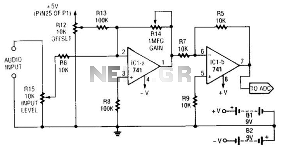
Audio-To-Adc Interface Circuit
This simple general-purpose driver for an analog/digital converter uses two 741 IC devices with adjustable gain and offset. Other op-amps might be substituted, but some circuit adjustments might be needed.
The circuit consists of two operational amplifiers (op-amps) from the 741...
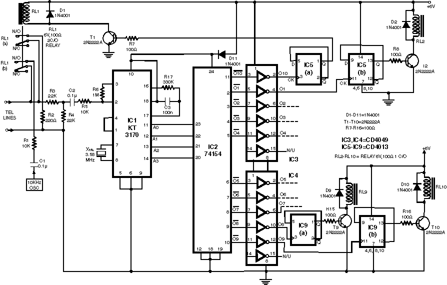
Telephone Remote control
Here is a teleremote circuit which enables switching on and off of appliances through telephone lines. It can be used to switch appliances from any distance, overcoming the limited range of infrared and radio remote controls. The circuit described here...
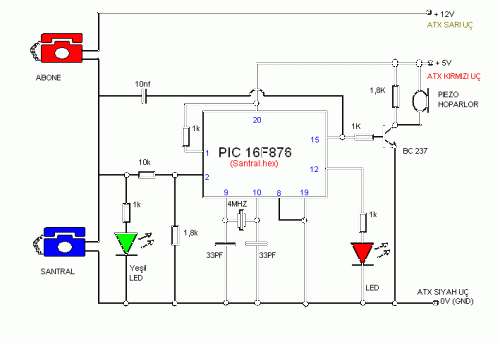
Simple Telephone Central Project
This simple telephone switching system is designed by Dr. Mustafa Kemal Peker for training purposes. All responsibility belongs to the user. Schematic and circuit details are included.
The telephone switching system designed for training purposes serves as an educational tool to...
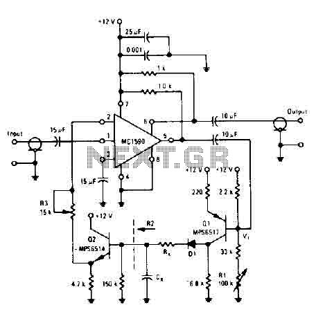
Audio compressor circuit
The amplifier drives the base of a common emitter PNP MPS6517, operating with a voltage gain of approximately 20. The RL control adjusts the quiescent point of transistor Q, allowing varying amounts of input signal to exceed the reference voltage...
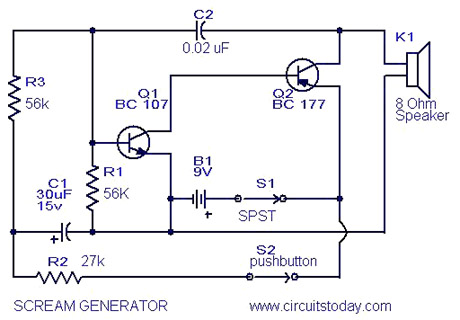
Tone Generator Circuits
Multi Tone Alarm Description This is a simple and easy-to-build multi-tone alarm circuit that can be used in burglar alarms or sirens. The circuit is based on the dual op-amp MC1458 and LM380. The two op-amps inside the MC1458 are...
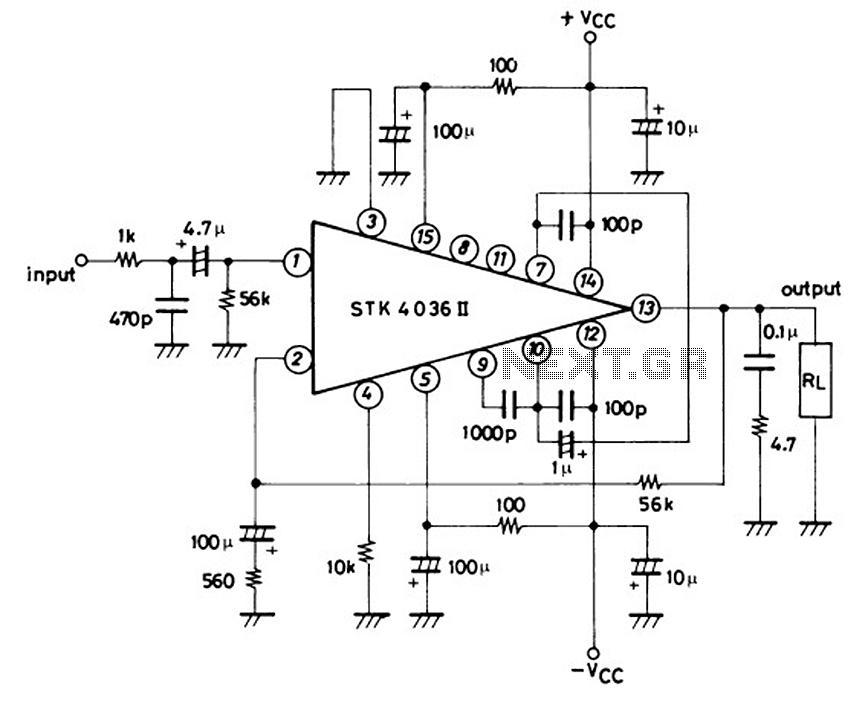
Schematic Diagram 50W TK4036II baseed Stereo Power Amplifier Circuitand explanation
This is a 50-watt audio power amplifier circuit based on the single IC STK4036II. A heatsink is required to prevent overheating of the IC. The amplifier circuit provides good sound quality at an affordable price and is easy to construct...
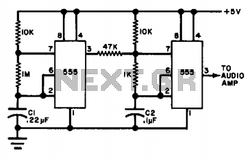
Tone generator
The circuit utilizes either two 555 timers or a single dual timer. Capacitor C1 regulates the speed of the warble effect, while capacitor C2 defines the pitch. The specified values are expected to generate a notably distinctive signal.
The described circuit...
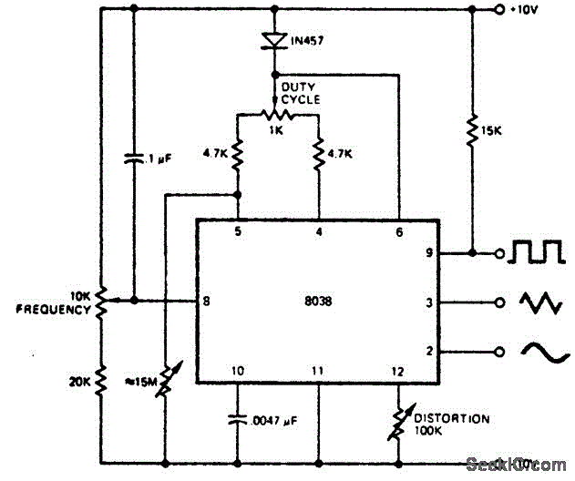
Variable_audio_oscillator_with_a_range_of_20_hertz_to_20_kilohertz
A variable audio oscillator operates within a frequency range of 20 hertz to 20 kilohertz. The circuit utilizes an Intersil 8038 waveform generator, which is designed in a 14-pin dual in-line package (DIP).
The variable audio oscillator circuit is designed to...

Telephone-line powered repertory dialer
A repertory dialer phone contains a library of phone numbers that can be entered and dialed, allowing access to up to fifteen frequently used numbers. It also includes the capability to store the last dialed number or an additional telephone...