


Two way Simple Very Small Telephone Exchange
#telephone exchange
#intercom
#ringing pulse
#bi-directional
#off hook detection
#telecommunication
#two-way communication
#connection establishment
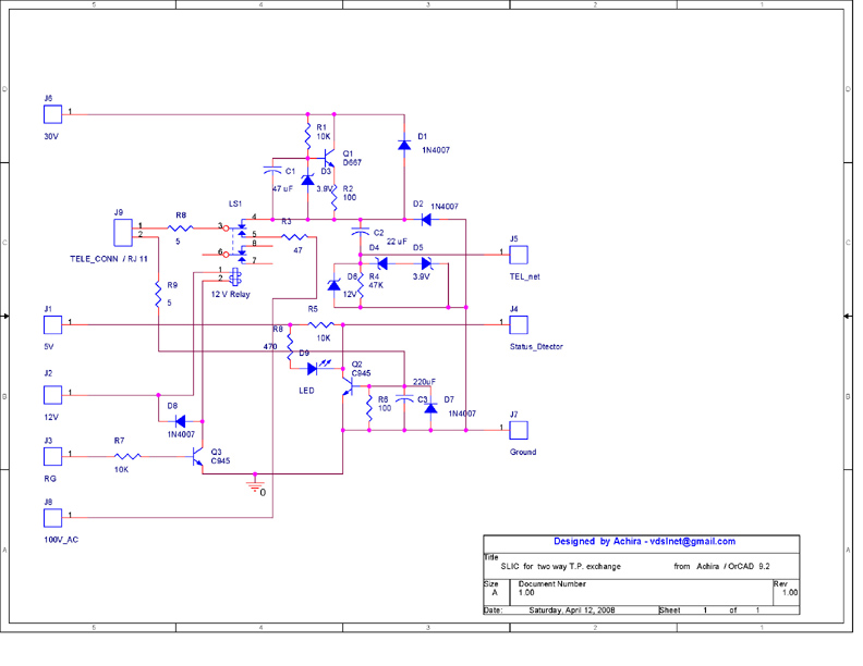
Description: This is a very small telephone exchange connected to two ordinary telephones. It features a fully bi-directional intercom system. When one phone is off-hook, the exchange detects this condition and sends a ringing pulse to the other phone. Once the second phone is picked up, a connection is established between both phones, and this process can occur in reverse as well. The circuit is based on the PIC16F84A microcontroller, with two similar Subscriber Line Interface Circuits (SLICs) connected to the controlling unit. The system must identify all connections on the controlling unit circuit diagram and is designed to detect every status from a standard telephone set for the controlling circuit (exchange). Two similar SLICs are required for this project.
The described circuit functions as a compact telephone exchange designed for two standard telephones, facilitating communication between them through an intercom system. The core of this design is the PIC16F84A microcontroller, which handles the logic and control functions necessary for the exchange's operation.
The operation begins when one of the telephones goes off-hook, indicating that the user wishes to initiate a call. The microcontroller detects this status change through the connected SLIC, which interfaces with the telephone line. Upon detection, the microcontroller sends a ringing pulse to the other telephone, alerting the user of an incoming call.
Once the second telephone is picked up, the microcontroller establishes a direct connection between the two phones, allowing for two-way communication. This bi-directional capability ensures that either phone can initiate a call, and the system is designed to handle this interchange seamlessly.
The design incorporates two SLICs, which are essential for interfacing the telephones with the controlling unit. These circuits manage the electrical characteristics of the telephone line, ensuring proper signaling and power delivery. The SLICs must be configured to recognize the status of the telephones, including off-hook and on-hook conditions, and relay this information back to the microcontroller.
In terms of connections, the controlling unit circuit diagram must clearly outline the integration points for the SLICs, the microcontroller, and the telephones. Proper identification of these connections is crucial for the successful implementation of the project. The design should also consider any necessary resistors, capacitors, and other passive components that may be required for stability and performance.
Overall, the circuit represents a practical application of microcontroller technology in telecommunications, providing a simple yet effective solution for direct phone-to-phone communication in a compact form factor.This is a very small telephone exchange attached only two ordinary Tele phones. Fully bi-directional facility with an intercom system. When a phone is in off hook condition, Exchange will detect it & send ringing pulse to other phone. When it will be picked up, the connection will be established between both phones. This will be taken place vice -versa. This circuit is base on PIC16F84A microcontroller. Two slimier SLIC are connected to The controlling unit. It needs to identify following connections on the controlling unit circuit diagram. This unit is required to detect every status from an usual telephone set for the Controlling circuit ( Exchange ). It interfaces an usual telephone to the controlling circuit. Two slimier SLIC are required for this project.
The described circuit functions as a compact telephone exchange designed for two standard telephones, facilitating communication between them through an intercom system. The core of this design is the PIC16F84A microcontroller, which handles the logic and control functions necessary for the exchange's operation.
The operation begins when one of the telephones goes off-hook, indicating that the user wishes to initiate a call. The microcontroller detects this status change through the connected SLIC, which interfaces with the telephone line. Upon detection, the microcontroller sends a ringing pulse to the other telephone, alerting the user of an incoming call.
Once the second telephone is picked up, the microcontroller establishes a direct connection between the two phones, allowing for two-way communication. This bi-directional capability ensures that either phone can initiate a call, and the system is designed to handle this interchange seamlessly.
The design incorporates two SLICs, which are essential for interfacing the telephones with the controlling unit. These circuits manage the electrical characteristics of the telephone line, ensuring proper signaling and power delivery. The SLICs must be configured to recognize the status of the telephones, including off-hook and on-hook conditions, and relay this information back to the microcontroller.
In terms of connections, the controlling unit circuit diagram must clearly outline the integration points for the SLICs, the microcontroller, and the telephones. Proper identification of these connections is crucial for the successful implementation of the project. The design should also consider any necessary resistors, capacitors, and other passive components that may be required for stability and performance.
Overall, the circuit represents a practical application of microcontroller technology in telecommunications, providing a simple yet effective solution for direct phone-to-phone communication in a compact form factor.This is a very small telephone exchange attached only two ordinary Tele phones. Fully bi-directional facility with an intercom system. When a phone is in off hook condition, Exchange will detect it & send ringing pulse to other phone. When it will be picked up, the connection will be established between both phones. This will be taken place vice -versa. This circuit is base on PIC16F84A microcontroller. Two slimier SLIC are connected to The controlling unit. It needs to identify following connections on the controlling unit circuit diagram. This unit is required to detect every status from an usual telephone set for the Controlling circuit ( Exchange ). It interfaces an usual telephone to the controlling circuit. Two slimier SLIC are required for this project.
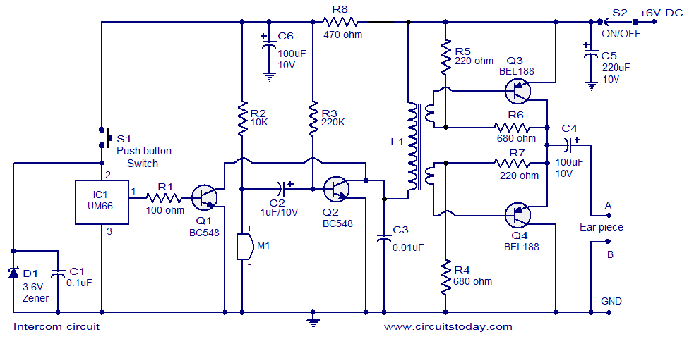
Two way intercom circuit diagram using transistors and UM66 as ringer
A straightforward intercom circuit designed using transistors. It does not require a changeover switch and can be used similarly to a telephone.
This intercom circuit utilizes transistors to facilitate communication between two or more stations without the need for complex switching...
Intercom Circuit
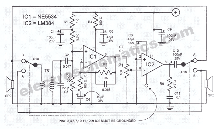
The intercom schematic provides a reliable communication line and is straightforward to construct. The circuit consists of an amplifier, two switches, and two loudspeakers. If additional stations (speakers) are desired, more switches can be incorporated into the circuit. The IC...
Intercom Circuit
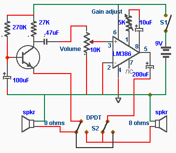
In this intercom schematic, an 8-ohm speaker is used as both a microphone and a listening speaker. A 10K potentiometer controls the volume, and the total gain can be adjusted.
This intercom circuit utilizes an 8-ohm speaker in a dual role,...
The Link 4+0 ?– Internal Intercoms
This version of the Link is intended for users who require an affordable and reliable intercom system without access to an external telephone line. It is suitable for environments such as preschools, hobby farms, or small workshops and factories, where...
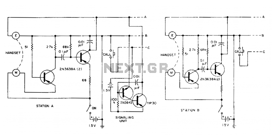
Party intercom
A large number of intercom stations can be connected in parallel. All units share a single signaling circuit for communication. Each station is powered independently by 1.5-V cells for redundancy, although 3-V sources can be utilized for increased signal volume...
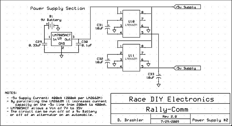
DIY Intercom Design Thread 5
This circuit utilizes the LM2662M integrated circuit from National Semiconductor, which serves as a direct replacement for the MAX1044 but in a smaller surface mount package. Additionally, the main voltage regulator has been upgraded to the LM7805ACT. This circuit is...
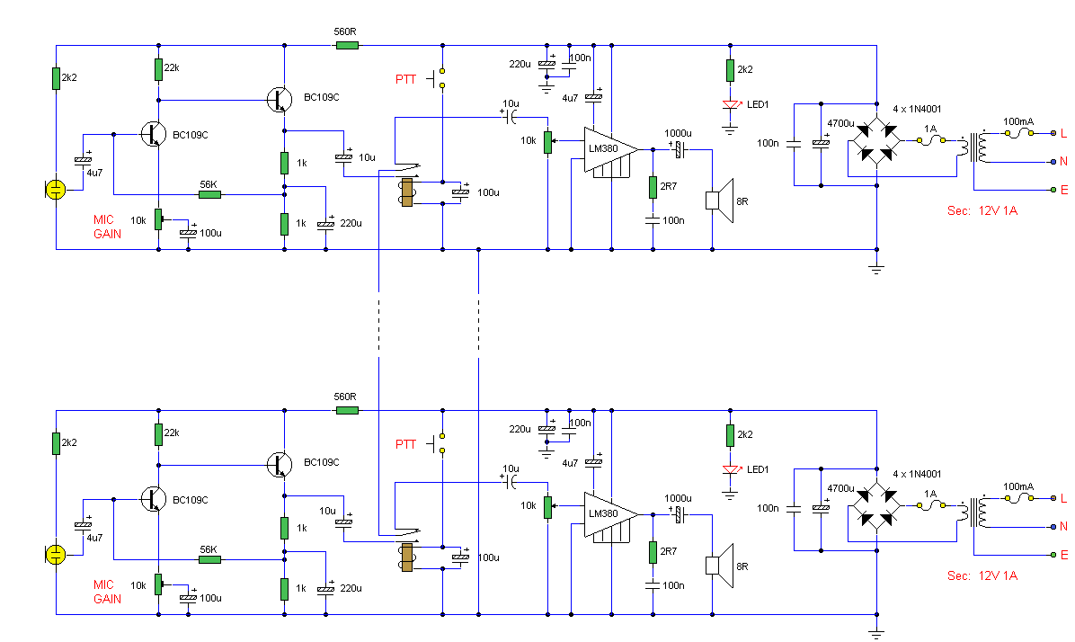
High Quality Intercom
This circuit consists of two identical intercom units. Each unit contains a power supply, microphone preamplifier, audio amplifier, and a Push To Talk (PTT) relay circuit. Only two wires are required to connect the units together. Due to the low...

One-Way Voice-Activated Intercom Circuit
An omnidirectional electret microphone is utilized to capture sound and convert it into an electrical signal. The output from the microphone is directed along two pathways. In the first pathway, the signal is routed to the inverting input at pin...
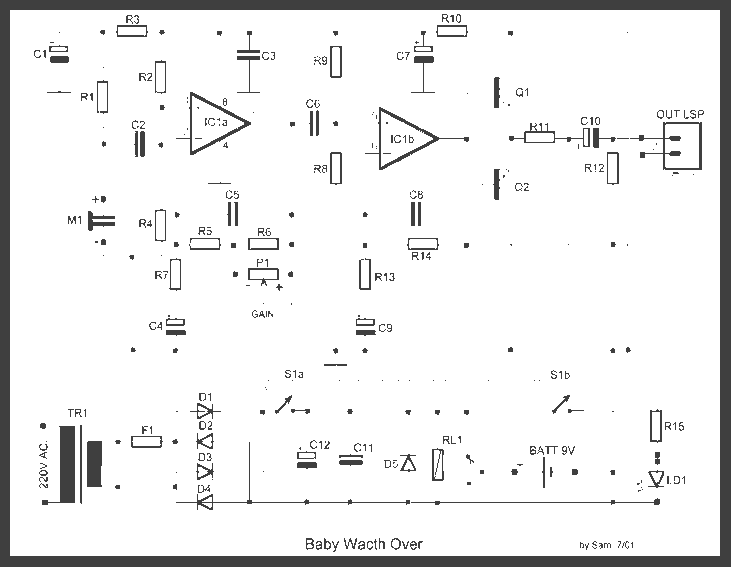
Baby watch Intercom Circuit
It's a very simple circuit, for the follow-up of baby. It can however be also used for other use, as intercom etc. In the place of M1 we can we use a simple electret mic capsule. The regulation of gain...