


U4076B Three-tone Ringer Telephone Sets
#U4076B
#three-tone ringer
#telephone
#piezo transducer
#loudspeaker
#ringing current
#integrated circuit
#communication
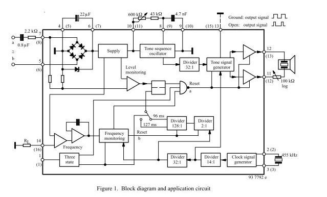
Description: The three-tone ringing integrated circuit U4076B, in conjunction with a piezo transducer or loudspeaker, replaces the normal electromechanical telephone bell. It is operated with the ringing current frequency.
The U4076B integrated circuit is designed to generate a three-tone ringing signal, which can effectively replace traditional electromechanical bells found in telecommunication devices. This circuit is particularly advantageous in applications where space and energy efficiency are critical. The U4076B operates by producing a sequence of three distinct tones that create an appealing auditory signal, enhancing the user experience compared to a single-tone bell.
The circuit requires a power supply that is compatible with the ringing current frequency, typically in the range of 20 Hz to 50 Hz, depending on the specific application and regional standards. The piezo transducer or loudspeaker connected to the U4076B is responsible for converting the electrical signals generated by the IC into audible sound. The choice of transducer can significantly affect the volume and quality of the ringing sound produced.
In terms of circuit design, the U4076B typically interfaces with a minimal number of external components, including resistors and capacitors, to set the tone frequencies and control the output signal. The output stage of the circuit may include a driver transistor to ensure sufficient power is supplied to the transducer for clear sound reproduction. The implementation of this integrated circuit allows for a compact and reliable solution for modern telephone systems, making it an excellent choice for both consumer and commercial applications.
Overall, the U4076B integrated circuit represents a significant advancement in ringing signal technology, providing a versatile and efficient alternative to traditional bell systems.The three-tone ringing integrated circuit U4076B in conjunction with a piezo transducer or loudspeaker replaces the normal electromechanical telephone bell. It is operated with the ringing current fr..
The U4076B integrated circuit is designed to generate a three-tone ringing signal, which can effectively replace traditional electromechanical bells found in telecommunication devices. This circuit is particularly advantageous in applications where space and energy efficiency are critical. The U4076B operates by producing a sequence of three distinct tones that create an appealing auditory signal, enhancing the user experience compared to a single-tone bell.
The circuit requires a power supply that is compatible with the ringing current frequency, typically in the range of 20 Hz to 50 Hz, depending on the specific application and regional standards. The piezo transducer or loudspeaker connected to the U4076B is responsible for converting the electrical signals generated by the IC into audible sound. The choice of transducer can significantly affect the volume and quality of the ringing sound produced.
In terms of circuit design, the U4076B typically interfaces with a minimal number of external components, including resistors and capacitors, to set the tone frequencies and control the output signal. The output stage of the circuit may include a driver transistor to ensure sufficient power is supplied to the transducer for clear sound reproduction. The implementation of this integrated circuit allows for a compact and reliable solution for modern telephone systems, making it an excellent choice for both consumer and commercial applications.
Overall, the U4076B integrated circuit represents a significant advancement in ringing signal technology, providing a versatile and efficient alternative to traditional bell systems.The three-tone ringing integrated circuit U4076B in conjunction with a piezo transducer or loudspeaker replaces the normal electromechanical telephone bell. It is operated with the ringing current fr..
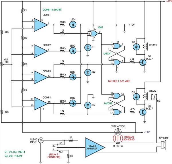
Loudspeaker Protector Monitors Current
This circuit utilizes a 0.1Ω 1W resistor connected in series with the output of a power amplifier. When the amplifier delivers 100W into an 8Ω load, the resistor dissipates 1.25W. The temperature rise is detected by a thermistor thermally bonded...
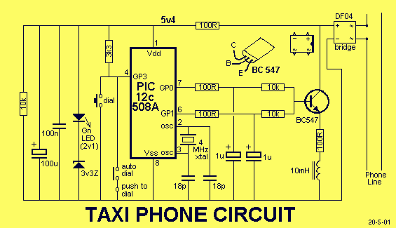
TAXI PHONE
This project is a dedicated device. It dials a single phone number when the handset is lifted. There are two different modes of operation. A slide-switch on the PC board allows the project to operate in automatic or manual mode....
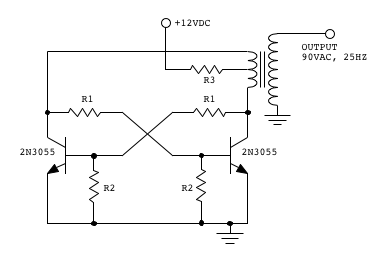
telephone ringer project
Make two telephones ring on stage. This involves sending a signal down a line to the phones. An old telephone exchange system was initially sought but not found. Several circuit ideas have been discovered, but the goal is to create...
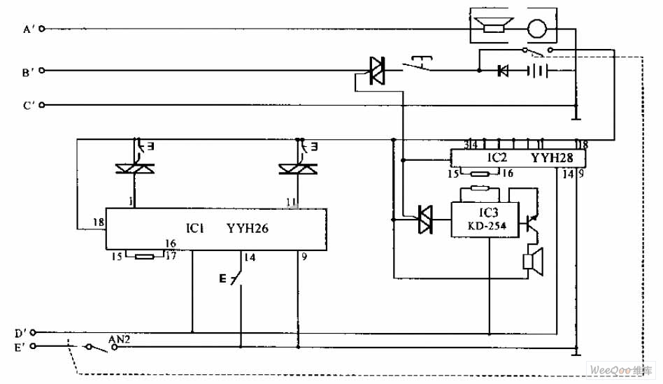
Internal telephone circuit
The internal telephone circuit is depicted below. By making minor enhancements to a toy telephone, it can be transformed into a functional internal telephone. This device comprises several components, including the phone unit, a decoding circuit, a ringing circuit, and...
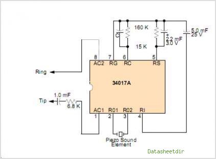
MC34017A Telephone Tone Ringer Bipolar Linear/I2L
It is widely recognized that power-saving regulations necessitate very low power consumption during standby conditions for all equipment continuously connected to mains power. In the standard version of the power supply, standby power consumption is approximately 9.0 W for a...
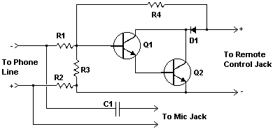
Telephone line monitor circuit
This compact circuit enables automatic recording of phone conversations. It connects to the phone line, the microphone input of a tape recorder, and the remote control jack of the recorder. The circuit detects the voltage level in the phone line...
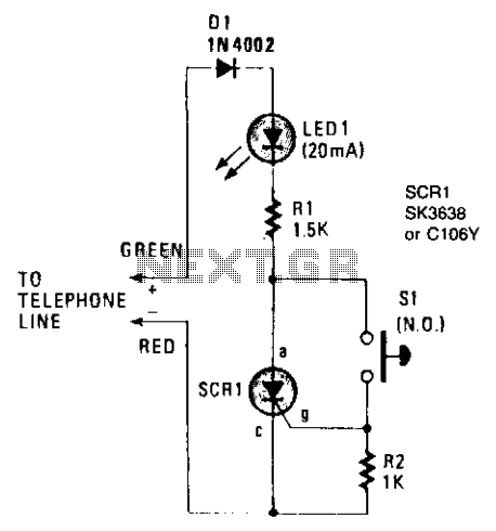
Telephone hold button
The on-hook (no load) voltage across the red-green wires will be 48 V or slightly less when all telephones are on-hook (disconnected). When any telephone goes off-hook, the load current flowing in the telephone causes the voltage to fall below...
The Original 2 Phone Link=
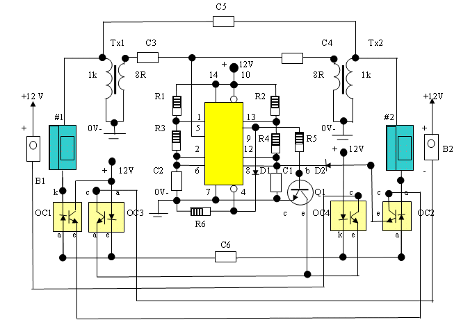
This circuit initiated the development of various Link Telephone Intercom designs. Originally created in 1996 using heavy-duty relays and contact banks, it was updated last year to incorporate IC1 in place of a simpler transistor multivibrator. All relays and contact...
Loudspeaker Tester
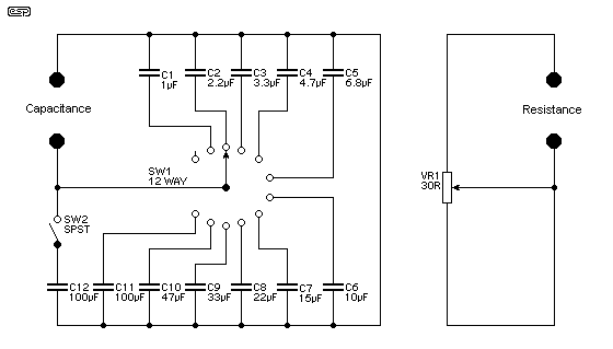
Testing loudspeakers is covered in some detail in the passive crossover article, but it is irksome at best to have to fiddle about with clip leads and components lying all over the workbench. This simple project is intended to make...