


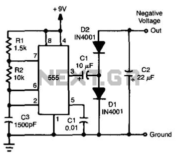
555 low power timing circuit diagram
#555 timer
#low power
#timing circuit
#pulse generator
#delay circuit
#electronics
#circuit diagram
#chinaicmart
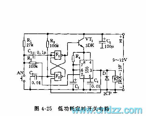
Description: 555 low power timing circuit diagram. The diagram is from the technical information of Chinaicmart. For more detailed information about the circuit diagram.
The 555 timer IC is widely utilized in various applications due to its versatility and ease of use. In a low power timing circuit configuration, the 555 timer can function in both astable and monostable modes, allowing it to generate precise timing intervals or oscillations.
In the astable mode, the circuit continuously oscillates between high and low states, producing a square wave output. This configuration requires two resistors (R1 and R2) and a capacitor (C1) connected to the threshold and discharge pins of the 555 timer. The frequency of oscillation and duty cycle can be calculated using the formulas:
Frequency (f) = 1.44 / ((R1 + 2 * R2) * C1)
Duty Cycle (%) = (R2 / (R1 + 2 * R2)) * 100
In monostable mode, the 555 timer generates a single pulse when triggered. The duration of the pulse is determined by a resistor (R) and a capacitor (C) connected to the timing pins. The pulse width can be calculated as:
Pulse Width (T) = 1.1 * R * C
To minimize power consumption, low value resistors and capacitors can be selected, and the timer can be powered using low voltage sources. Additionally, the use of bypass capacitors near the power supply pins can help reduce noise and improve circuit stability.
The application of the 555 low power timing circuit can be found in timer applications, pulse generation, LED flashing circuits, and many other timing-related tasks. Proper layout and grounding techniques should be employed to ensure optimal performance and minimize interference.555 low power timing circuit diagram The diagram is from the tech information of chinaicmart. IF for more detailed infomation of the circuit diagram..
The 555 timer IC is widely utilized in various applications due to its versatility and ease of use. In a low power timing circuit configuration, the 555 timer can function in both astable and monostable modes, allowing it to generate precise timing intervals or oscillations.
In the astable mode, the circuit continuously oscillates between high and low states, producing a square wave output. This configuration requires two resistors (R1 and R2) and a capacitor (C1) connected to the threshold and discharge pins of the 555 timer. The frequency of oscillation and duty cycle can be calculated using the formulas:
Frequency (f) = 1.44 / ((R1 + 2 * R2) * C1)
Duty Cycle (%) = (R2 / (R1 + 2 * R2)) * 100
In monostable mode, the 555 timer generates a single pulse when triggered. The duration of the pulse is determined by a resistor (R) and a capacitor (C) connected to the timing pins. The pulse width can be calculated as:
Pulse Width (T) = 1.1 * R * C
To minimize power consumption, low value resistors and capacitors can be selected, and the timer can be powered using low voltage sources. Additionally, the use of bypass capacitors near the power supply pins can help reduce noise and improve circuit stability.
The application of the 555 low power timing circuit can be found in timer applications, pulse generation, LED flashing circuits, and many other timing-related tasks. Proper layout and grounding techniques should be employed to ensure optimal performance and minimize interference.555 low power timing circuit diagram The diagram is from the tech information of chinaicmart. IF for more detailed infomation of the circuit diagram..
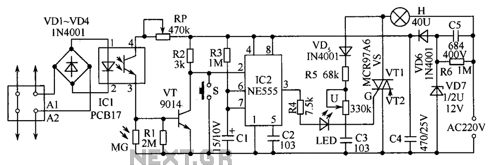
Sound delay lamp circuit diagram
The telephone table lamp is designed to automatically illuminate during night ringing or when the phone is off-hook. After hanging up, the lamp will extinguish after a delay of 45 seconds. It is typically used as a general-purpose lamp with...
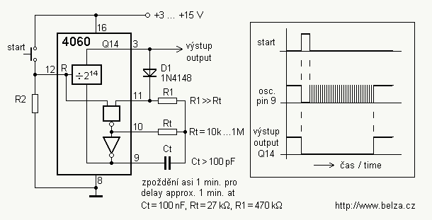
Delay circuit for a long time periods ( 4060 )
If you need a timer circuit, we go after the most proven 555. However, if the delays are longer, based on timing capacitor capacity is too large. In this case, a circuit of Figure 1 After pressing the button -...
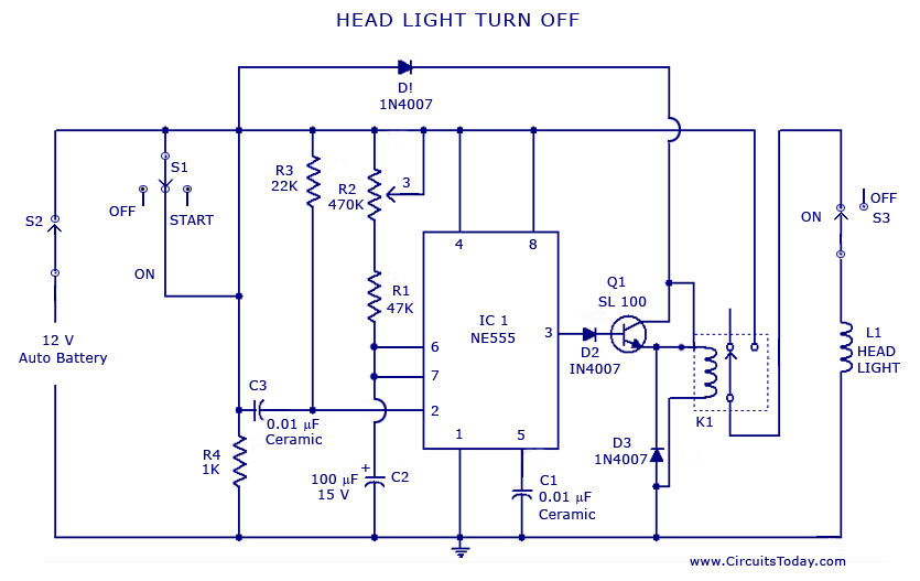
Automatic Car/Vehicle Head Lights Turn Off Circuit
A circuit that can automatically turn off the headlights or lamps of a vehicle after a preset time. This light switching circuit is constructed using a 555 timer integrated circuit (IC).
The described circuit utilizes the 555 timer IC in a...
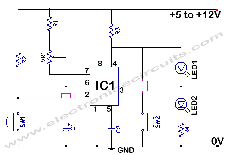
555 Timer Time Delay Circuit
The 555 Timer Time Delay Circuit uses LEDs to visually indicate the status of the circuit at any moment. The operation begins when the reset switch, SW2, is activated.
The 555 Timer is a versatile integrated circuit widely used for generating...
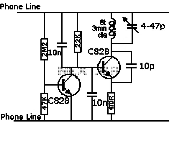
audio frequency meter
This is a circuit for an audio frequency meter. This circuit utilizes a 555 IC configured as a monostable multivibrator (one-shot trigger). A monostable multivibrator can function as a frequency-to-voltage converter by producing a fixed pulse width, with the repetition...

Flashing LEDs toy with 555
There have described the involvement benefited LM3909 circuit, which is quite expensive. That's why I prefer to use a much cheaper known timer 555th. Involvement of the tree is a very simple scheme is to figure 2. It is based...
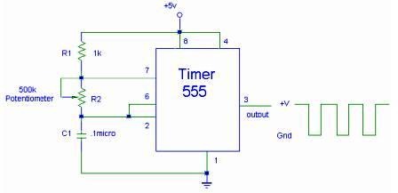
555 Timer IC for Square Wave Generator Application
The setup for the Square Wave Generator can be initiated using a 555 timer IC as illustrated in the accompanying circuit diagram. It is essential to reference the pinout configuration of the 555 timer IC. An oscilloscope should be connected...
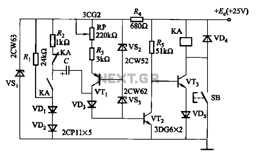
Charging time relay circuit 2
Charging time relay circuit 2 is a long delay circuit. When the capacitor C is 5000 µF, the delay can be up to 1.3 hours. Transistors VT1 and the VS2, VS3 group function as a constant current source to improve...
Negative Voltage From A Positive Supply
By utilizing a 555 timer to produce a square wave and employing a voltage-doubling technique on the output, a negative voltage that is nearly equivalent to the positive supply can be achieved. The available current ranges from 20 to 30...