


A digital display timer circuit diagram
#digital timer
#display
#pulse signal
#decoding
#digital display tube
#time measurement
#countdown
#precision timing
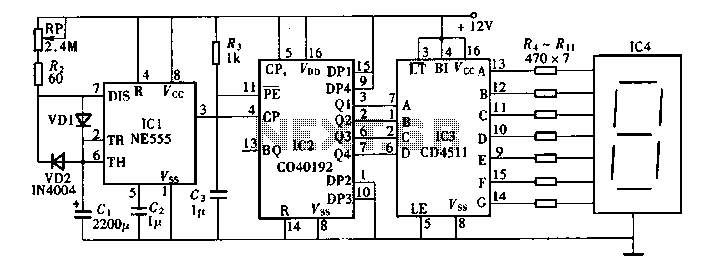
Description: Digital timers feature a clear and precise display. They represent time intervals based on pulse signals, which are decoded by a digital device with a digital display unit. The circuit described pertains to a digital display for these timers, which operates according to a time base signal that can be in seconds or other divisions of time. However, achieving accuracy with this circuit structure can be challenging, leading to infrequent use. The circuit includes a generator circuit that produces the base signal, a time counter, digital decoders, and digital display components.
The digital timer circuit operates by utilizing a pulse signal generated by an oscillator or clock circuit. This pulse signal serves as the time base, which is essential for counting time intervals accurately. The time counter is typically implemented using flip-flops or binary counters, which increment their count with each pulse received from the oscillator.
The digital decoders are responsible for converting the binary output from the time counter into a format suitable for the display unit. Commonly, a 7-segment display is employed, where each segment corresponds to a specific binary input. The decoder translates the binary count into the appropriate segments to illuminate, thus visually representing the elapsed time.
The overall accuracy of the digital timer can be influenced by several factors, including the stability of the oscillator, the precision of the time counter, and the quality of the digital decoders. To enhance accuracy, it is advisable to use high-frequency oscillators and well-calibrated counters.
In practical applications, digital timers are widely used in various fields, including industrial automation, laboratory experiments, and consumer electronics. The design of the circuit can be tailored to meet specific requirements, such as adjusting the time base for different time intervals or incorporating additional features like alarm functions or countdown capabilities.
The schematic representation of this digital timer circuit would include the oscillator circuit, the time counter, the digital decoder, and the display unit, clearly indicating the connections and component values necessary for proper operation. Each component's role within the circuit is crucial for ensuring that the timer functions accurately and reliably.Digital timers with a display clear and precise features. It is a number that represents the time after the pulse signal by decoding the digital device with digital display tub e display. The circuit described is a digital display of the digital timers, its display unit according to the unit time base signal may be. It can be a second, can be divided, of course, also be time. But for a number of explicit timers, the when this unit too, due to this circuit structure, not easy to achieve accurate, it is seldom used.
Its circuit as shown in FIG. The base signal generated by the generator circuit, the time counter, digital decoders and digital display components.
The digital timer circuit operates by utilizing a pulse signal generated by an oscillator or clock circuit. This pulse signal serves as the time base, which is essential for counting time intervals accurately. The time counter is typically implemented using flip-flops or binary counters, which increment their count with each pulse received from the oscillator.
The digital decoders are responsible for converting the binary output from the time counter into a format suitable for the display unit. Commonly, a 7-segment display is employed, where each segment corresponds to a specific binary input. The decoder translates the binary count into the appropriate segments to illuminate, thus visually representing the elapsed time.
The overall accuracy of the digital timer can be influenced by several factors, including the stability of the oscillator, the precision of the time counter, and the quality of the digital decoders. To enhance accuracy, it is advisable to use high-frequency oscillators and well-calibrated counters.
In practical applications, digital timers are widely used in various fields, including industrial automation, laboratory experiments, and consumer electronics. The design of the circuit can be tailored to meet specific requirements, such as adjusting the time base for different time intervals or incorporating additional features like alarm functions or countdown capabilities.
The schematic representation of this digital timer circuit would include the oscillator circuit, the time counter, the digital decoder, and the display unit, clearly indicating the connections and component values necessary for proper operation. Each component's role within the circuit is crucial for ensuring that the timer functions accurately and reliably.Digital timers with a display clear and precise features. It is a number that represents the time after the pulse signal by decoding the digital device with digital display tub e display. The circuit described is a digital display of the digital timers, its display unit according to the unit time base signal may be. It can be a second, can be divided, of course, also be time. But for a number of explicit timers, the when this unit too, due to this circuit structure, not easy to achieve accurate, it is seldom used.
Its circuit as shown in FIG. The base signal generated by the generator circuit, the time counter, digital decoders and digital display components.
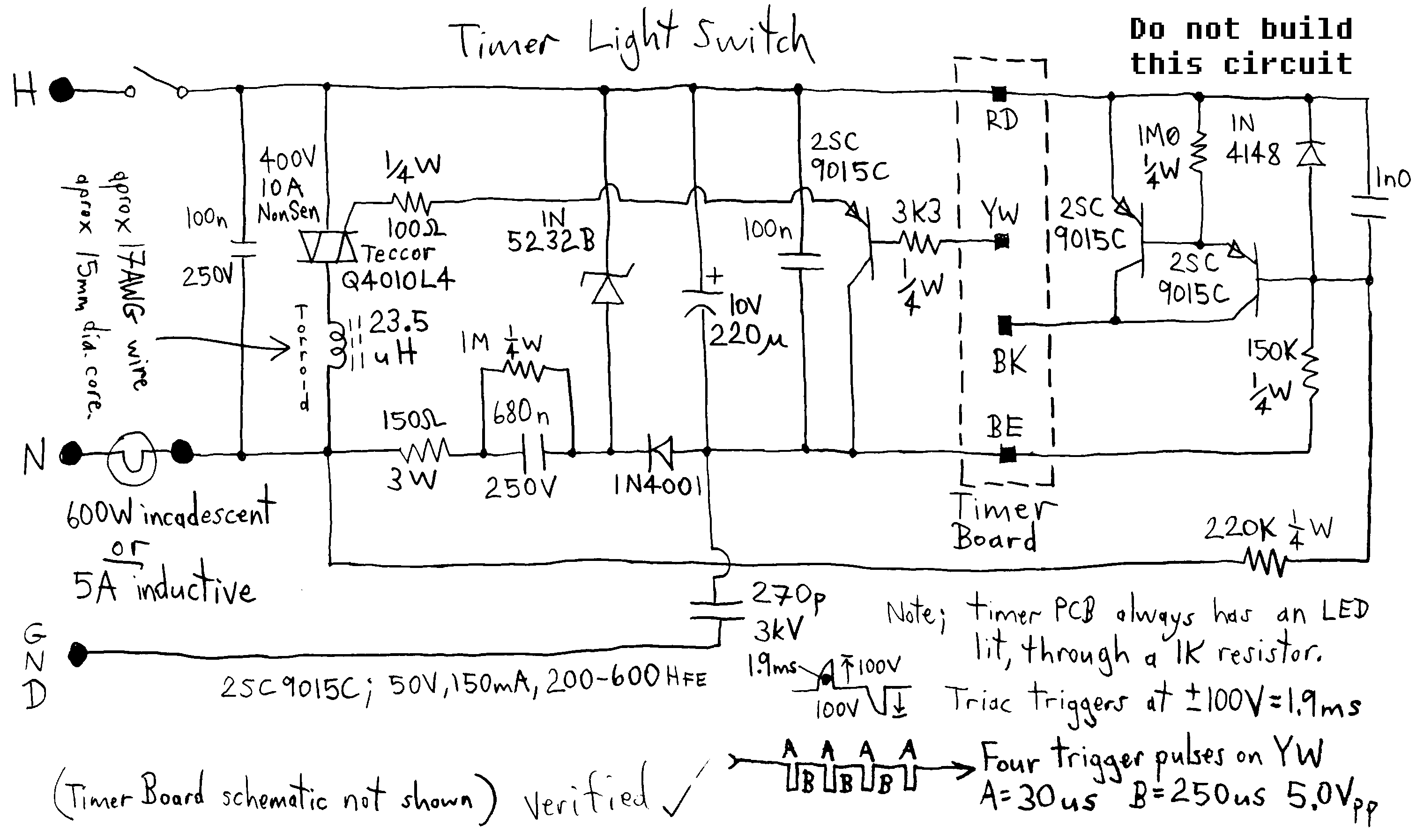
Digital Timer Light Switch
Typical circuit representative of those used in most light switch type digital timers. The timer module is normally a PIC or custom chip, and it syncs to the AC line so that a trigger pulse can be supplied at the...
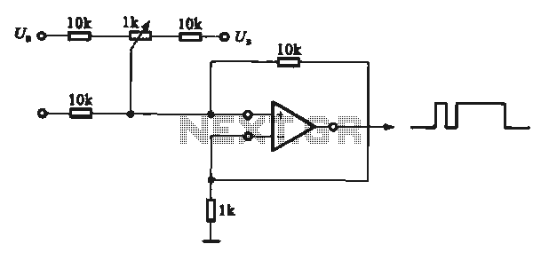
Pulse signal generating circuit
This circuit demonstrates the application of various types of pulse signal generating circuits using operational amplifiers.
The circuit utilizes operational amplifiers (op-amps) to create different forms of pulse signals, which are essential in many electronic applications, including waveform generation, timing circuits,...
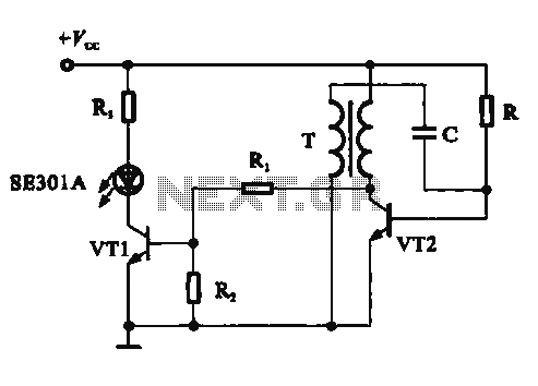
Pulse signal generating circuit and display
This circuit demonstrates a dynamic AC signal level display drive, which can be utilized for audio level display purposes. The AC signal detection and drive control are achieved using the BA6124 integrated circuit, along with five external colored light-emitting diodes...
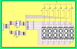
display and serial interfacing of
This hardware is designed to display the number of cars in a parking lot. The system utilizes a six-segment display; however, a single display is sufficient for the intended function. It employs the segment driver IC SN7447AN along with a...
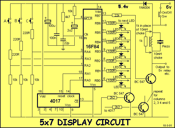
5x7 DISPLAY
You must be able to recognise components such as capacitors, diodes, zeners, transistors and resistors to build a 5x7 Display project. This information is covered in our BASIC ELECTRONICS course and a complete set of circuit symbols can be found...
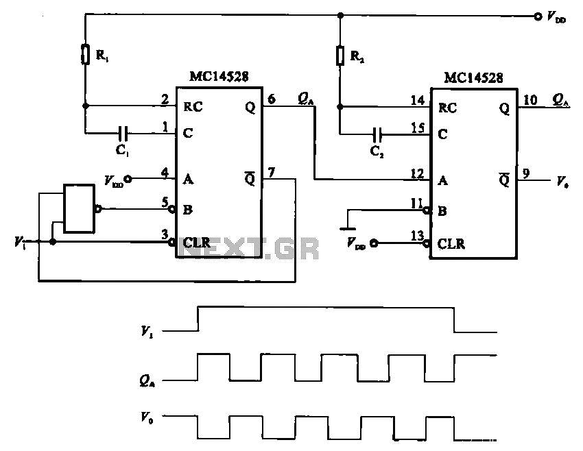
Monitoring by the pulse signal constituting the single-shot generating circuit
The pulse generating circuit monitors signals using monostable flip-flops. It generates a single-shot output signal based on the input pulse signal. A key signal from the monostable flip-flops is represented in a formula, with the input (V1) and output (V0,...

Pulse signal generating circuit
It demonstrates the use of various types of pulse signal generating circuits utilizing operational amplifiers.
The circuit described involves the implementation of pulse signal generators using operational amplifiers (op-amps), which are versatile components frequently employed in analog electronics. These circuits can...
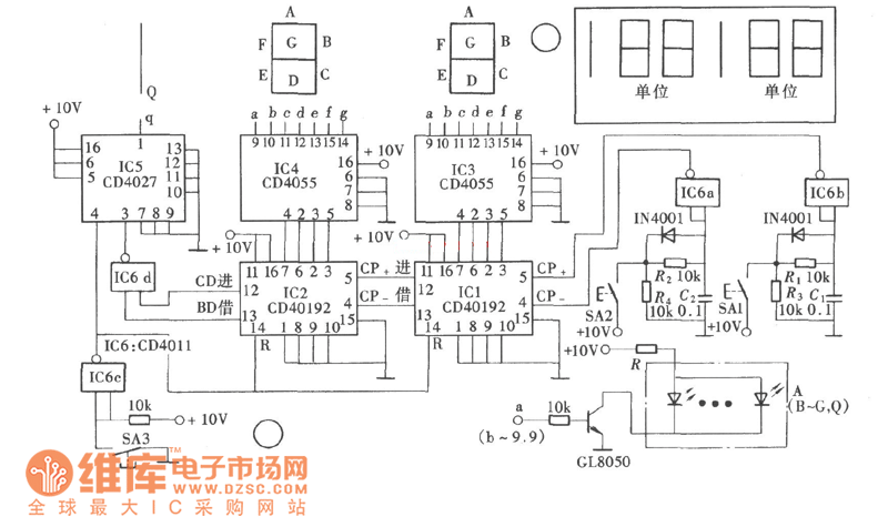
Game-scoring Display ScreenCircuit
The game-scoring display screen circuit diagram is depicted in the image above. The circuit consists of an add/subtract scoring input circuit, an add/subtract scoring circuit, a counting-decoding display circuit, and a reset circuit.
The game-scoring display circuit is designed to facilitate...
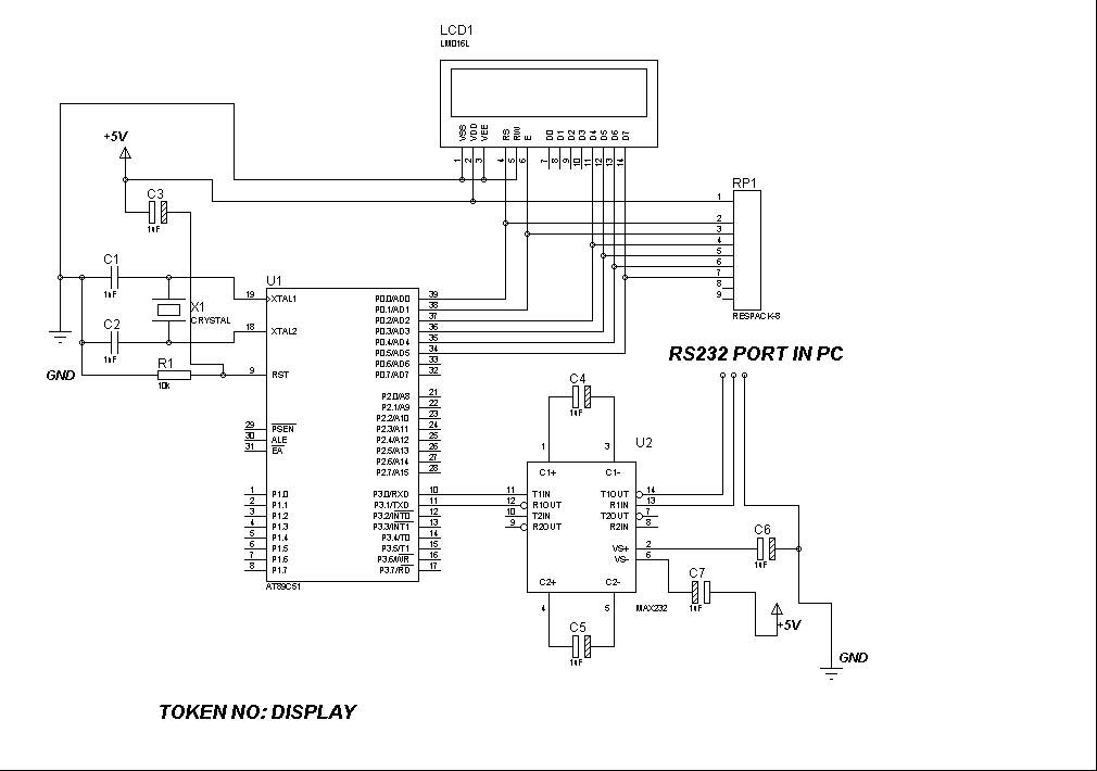
Token number display
Introduction: Token Display Systems are ideal for banks, airports, public dealing offices, hospitals, doctors' clinics, restaurants, and other locations where people must wait in line. These systems allow customers to wait comfortably without standing in line; they only need to...