


Auto OFF Light
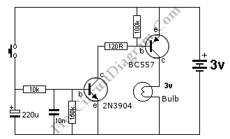
Description: This is an Auto OFF Light circuit. After the switch is pressed, the bulb remains illuminated for a few seconds. To increase the ON time, a 10k resistor should be used.
The Auto OFF Light circuit is designed to provide a temporary illumination of a bulb after a switch is activated. The operation of the circuit relies on a timing mechanism that allows the bulb to remain lit for a predetermined duration, enhancing user convenience in various applications, such as in hallways or bathrooms.
The core components of this circuit typically include a switch, a resistor (10kΩ), a capacitor, and a light bulb. When the switch is pressed, it initiates the charging of the capacitor through the resistor. The time the bulb stays lit is primarily determined by the RC time constant, which is a product of the resistance (R) and capacitance (C) in the circuit.
To increase the ON time, the value of the resistor can be adjusted. A higher resistance, such as 10kΩ, will result in a longer charging time for the capacitor, thus extending the duration the bulb remains illuminated. The formula for the time constant (τ) is given by τ = R × C, where τ is the time in seconds, R is the resistance in ohms, and C is the capacitance in farads.
The circuit may also include a diode to prevent back EMF from damaging components when the bulb is turned off. The light bulb can be of various types, including incandescent or LED, depending on the desired brightness and energy efficiency.
In summary, the Auto OFF Light circuit is a practical design that provides temporary lighting, with the ability to adjust the duration of illumination through component selection, making it suitable for a variety of lighting applications.This is Auto OFF Light circuit. After the switch is pressed, the bulb is kept illuminated for a few seconds. To increase the ON time, The 10k should be.
The Auto OFF Light circuit is designed to provide a temporary illumination of a bulb after a switch is activated. The operation of the circuit relies on a timing mechanism that allows the bulb to remain lit for a predetermined duration, enhancing user convenience in various applications, such as in hallways or bathrooms.
The core components of this circuit typically include a switch, a resistor (10kΩ), a capacitor, and a light bulb. When the switch is pressed, it initiates the charging of the capacitor through the resistor. The time the bulb stays lit is primarily determined by the RC time constant, which is a product of the resistance (R) and capacitance (C) in the circuit.
To increase the ON time, the value of the resistor can be adjusted. A higher resistance, such as 10kΩ, will result in a longer charging time for the capacitor, thus extending the duration the bulb remains illuminated. The formula for the time constant (τ) is given by τ = R × C, where τ is the time in seconds, R is the resistance in ohms, and C is the capacitance in farads.
The circuit may also include a diode to prevent back EMF from damaging components when the bulb is turned off. The light bulb can be of various types, including incandescent or LED, depending on the desired brightness and energy efficiency.
In summary, the Auto OFF Light circuit is a practical design that provides temporary lighting, with the ability to adjust the duration of illumination through component selection, making it suitable for a variety of lighting applications.This is Auto OFF Light circuit. After the switch is pressed, the bulb is kept illuminated for a few seconds. To increase the ON time, The 10k should be.
Repeating Timer 5
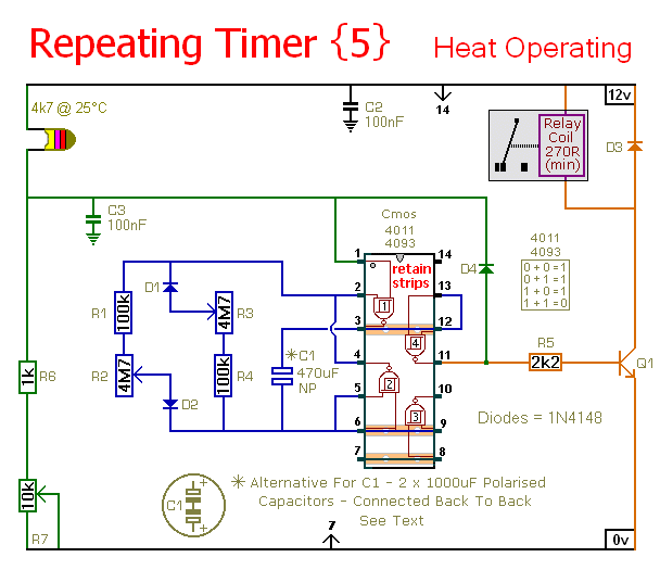
This timer circuit operates only when the temperature exceeds a predetermined level. An alternative version, known as Repeating Timer No. 6, functions while the temperature is below this preset level. The resistor R7 is used to set the temperature threshold....
Timer Garage Door Circuit Schematic Diagram
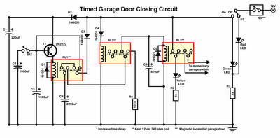
Timer garage door circuit schematic diagram, printed circuit board.
The timer garage door circuit is designed to automate the opening and closing of a garage door based on a predetermined time interval. The schematic diagram illustrates the layout and connections of...
The switch shut off time delay circuit diagram
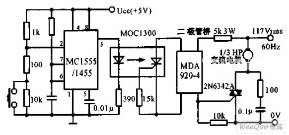
The switch shut-off time delay circuit consists of a timer, optocouplers, a bridge SCR, and an SCR AC switch. When the control button is released, it allows the motor or other AC power to remain active for one hour. Upon...
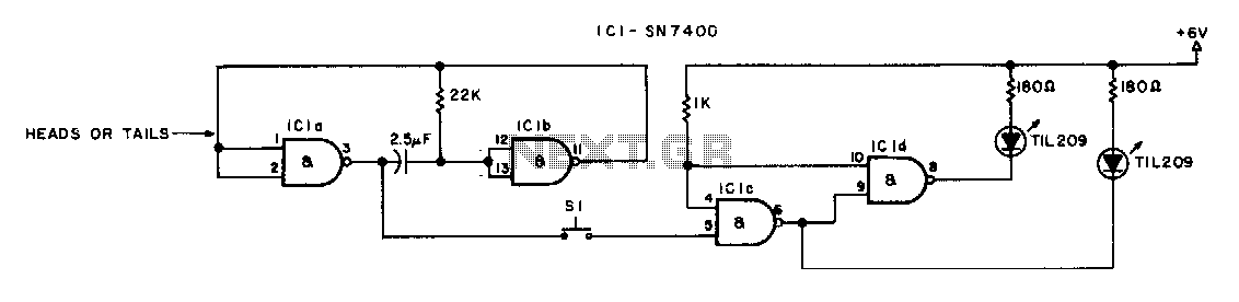
heads or tails
The switch must be a push-to-make, release-to-break type.
An effective circuit utilizing a push-to-make, release-to-break switch can be designed for various applications, particularly in control systems where momentary activation is required. This type of switch, often referred to as a momentary...
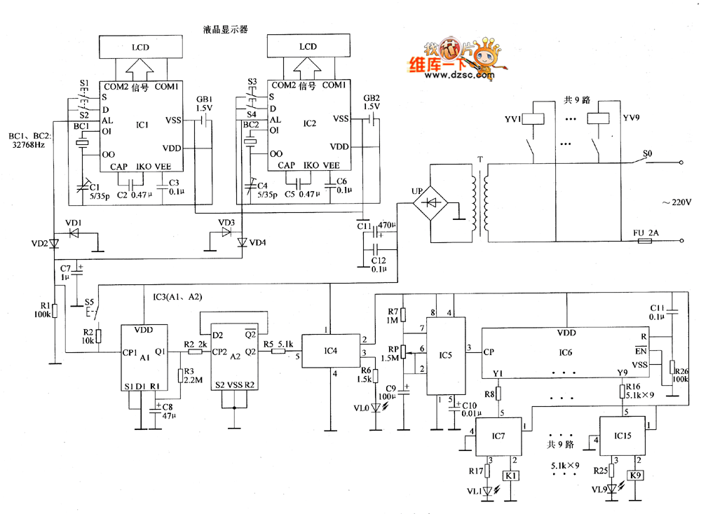
Automatic sprinkler controller circuit diagram 1
The automatic sprinkler controller circuit consists of a clock timing controller, a monostable flip-flop, a bistable flip-flop, an electronic switch, a self-excited multivibrator, a counter, a solenoid valve control circuit, and a power supply circuit. The power supply circuit includes...
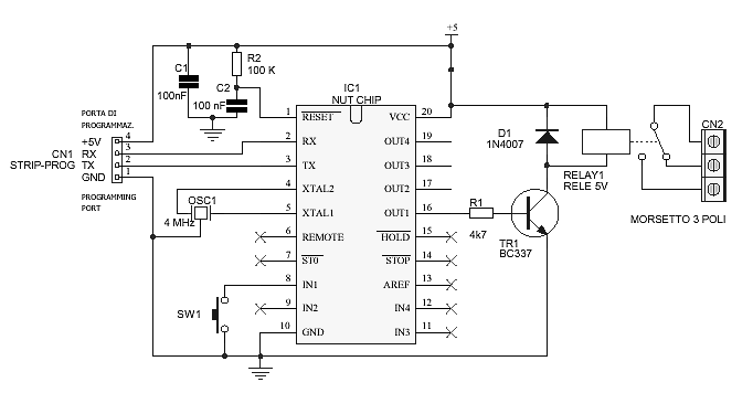
Timer circuit
The schematic diagram is straightforward. SW1 is a pushbutton used to start the timer. The outputs are set to logic level 0 when the timer is inactive and to logic level 1 when the timer is triggered. The relay driver...
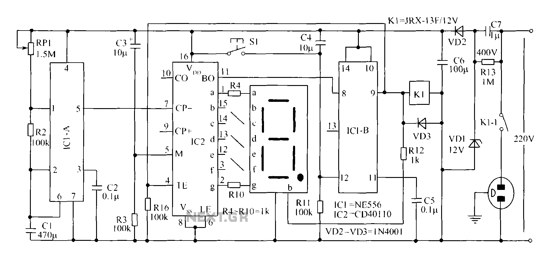
Novel circuit diagram of the timer switch
A novel timing switch circuit features a "Variable Timing" adjustment function in addition to a standard timing circuit. It also includes a countdown display feature, which indicates the remaining time of the timing circuit, making it particularly useful. The entire...
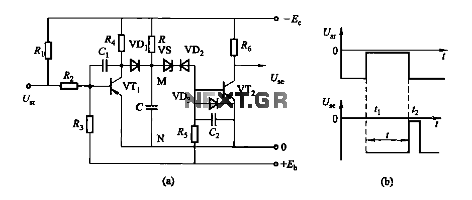
Conducting pipe control rechargeable delay circuit
The circuit features a delay action with an instantaneous reset control mechanism. It is categorized into three types: a conducting pipe rechargeable delay circuit, a tube cut-off control rechargeable delay circuit, and a discharge-type delay circuit. In the conducting pipe...
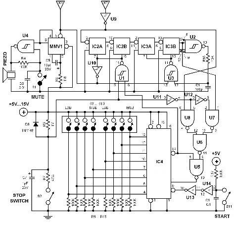
universal timer
The time interval of this circuit can be varied digitally through the DIP switches. The time code must be set in BCD form. A 120 Hz signal generated by doubling the line frequency is used as the time reference. This...