


FET relay circuit 2
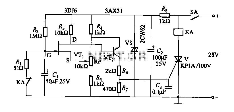
Description: FET relay circuit 2 is essentially a JS-20 time relay circuit. When the switch SA is open, the relay device KA remains in the released state. Once switch SA is closed, the delay period begins. After a specified duration, the thyristor activates, causing relay KA to engage. The adjustment potentiometer RP allows for modification of the delay time.
The FET relay circuit, designated as the JS-20 time relay, operates by utilizing a field-effect transistor (FET) as a control element to manage the timing function of the relay. The circuit is designed to maintain the relay in a deactivated state when the switch SA is open. This is achieved by ensuring that no current flows through the relay coil, thereby keeping the relay device KA in its released state.
Upon closing switch SA, the circuit initiates a delay sequence. During this delay, the capacitor in the timing circuit begins to charge through a resistor, forming an RC time constant that determines the duration of the delay. The time taken for the capacitor to charge to a specific voltage level is what ultimately dictates when the thyristor will be triggered.
Once the capacitor reaches the required voltage, the thyristor is activated, allowing current to flow through the relay coil. This activation pulls in relay KA, switching the connected load on. The delay time can be adjusted by varying the resistance of potentiometer RP, which alters the RC time constant. By increasing the resistance, the time delay increases, while decreasing it shortens the delay.
The circuit may also include additional components such as diodes for flyback protection to prevent voltage spikes when the relay coil is de-energized. Overall, this FET relay circuit provides a reliable and adjustable timing mechanism suitable for various applications where controlled delay activation is necessary.FET relay circuit 2 It is actually a JS-20 time relay circuit. SA before the switch is closed, the relay device KA tends to release state. After SA closed circuit delay start, after a period of time, the thyristor is turned on, KA pull. Adjustment potentiometer RP, can change the delay time.
The FET relay circuit, designated as the JS-20 time relay, operates by utilizing a field-effect transistor (FET) as a control element to manage the timing function of the relay. The circuit is designed to maintain the relay in a deactivated state when the switch SA is open. This is achieved by ensuring that no current flows through the relay coil, thereby keeping the relay device KA in its released state.
Upon closing switch SA, the circuit initiates a delay sequence. During this delay, the capacitor in the timing circuit begins to charge through a resistor, forming an RC time constant that determines the duration of the delay. The time taken for the capacitor to charge to a specific voltage level is what ultimately dictates when the thyristor will be triggered.
Once the capacitor reaches the required voltage, the thyristor is activated, allowing current to flow through the relay coil. This activation pulls in relay KA, switching the connected load on. The delay time can be adjusted by varying the resistance of potentiometer RP, which alters the RC time constant. By increasing the resistance, the time delay increases, while decreasing it shortens the delay.
The circuit may also include additional components such as diodes for flyback protection to prevent voltage spikes when the relay coil is de-energized. Overall, this FET relay circuit provides a reliable and adjustable timing mechanism suitable for various applications where controlled delay activation is necessary.FET relay circuit 2 It is actually a JS-20 time relay circuit. SA before the switch is closed, the relay device KA tends to release state. After SA closed circuit delay start, after a period of time, the thyristor is turned on, KA pull. Adjustment potentiometer RP, can change the delay time.
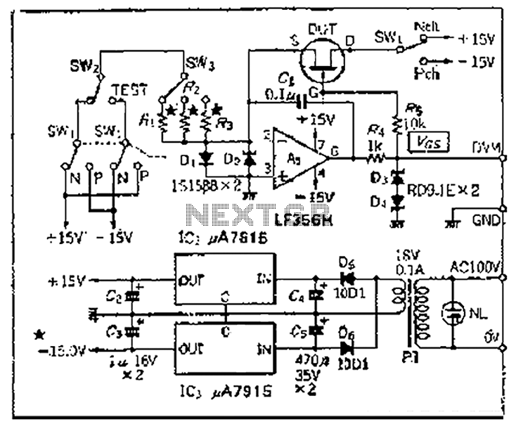
Used in conjunction with multimeters FET Vp Vas checker
Chen is in the operational amplifier circuit, utilizing a feedback loop with input resistance that determines the current roll-off. The FET drain current is controlled by the determination circuit, which provides the necessary voltage. The output constitutes a fake blood...
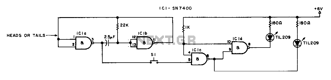
heads or tails
The switch must be a push-to-make, release-to-break type.
An effective circuit utilizing a push-to-make, release-to-break switch can be designed for various applications, particularly in control systems where momentary activation is required. This type of switch, often referred to as a momentary...
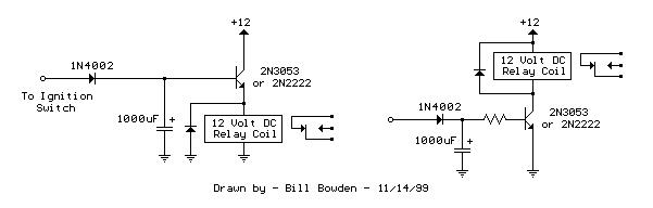
power off time delay relay
The two circuits demonstrate the process of opening a relay contact shortly after the ignition or light switch is turned off. The capacitor becomes charged, and the relay remains closed until the voltage at the diode anode reaches +12 volts.
The...
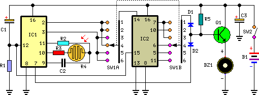
tan timer schematics
This timer is intended for individuals seeking to achieve a tan while minimizing excessive exposure to sunlight. A rotary switch adjusts the timer based on six categorized photo-types. A photoresistor modifies the preset time value in relation to sunlight brightness....
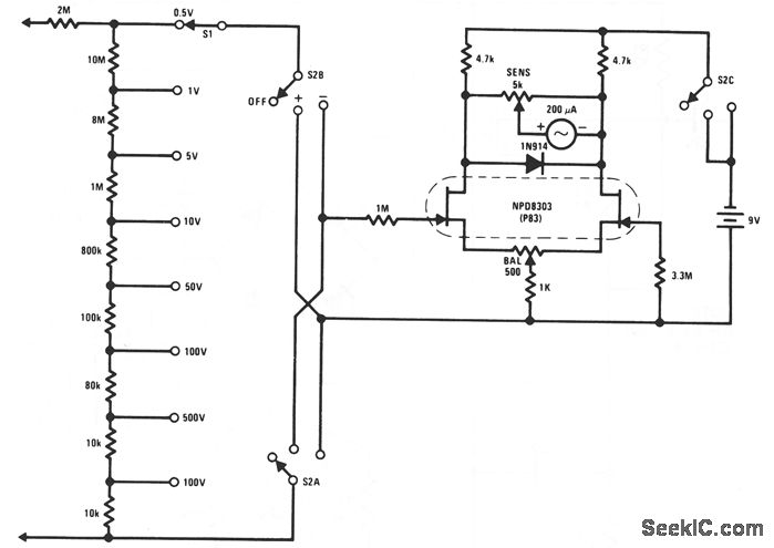
FET VOLTMETER 1
This FET voltmeter (FETVM) serves as a replacement for the vacuum tube voltmeter (VTVM) and eliminates the need for a standard line cord. Additionally, the drift rates of field-effect transistors (FETs) are significantly better than those of vacuum tube circuits,...
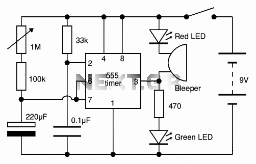
Adjustable Timer circuit 1-10 minute
The Adjustable Timer circuit initiates timing upon activation. A green LED illuminates to indicate that timing is in progress. Once the designated time period elapses, the green LED turns off, the red LED activates, and an audible bleeper sounds. The...
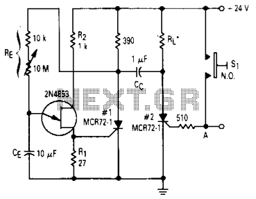
Timer circuit
After one cycle of operation, SCR1 will be activated, resulting in a low voltage being applied to the UJT emitter circuit, which interrupts the tuning function. When pushbutton SI is pressed, or a positive pulse is applied at point A,...

repeating interval timer
This circuit features an adjustable output timer that can re-trigger at specified intervals. The output duration can range from a fraction of a second to over half an hour, with the ability to repeat at consistent intervals from seconds to...
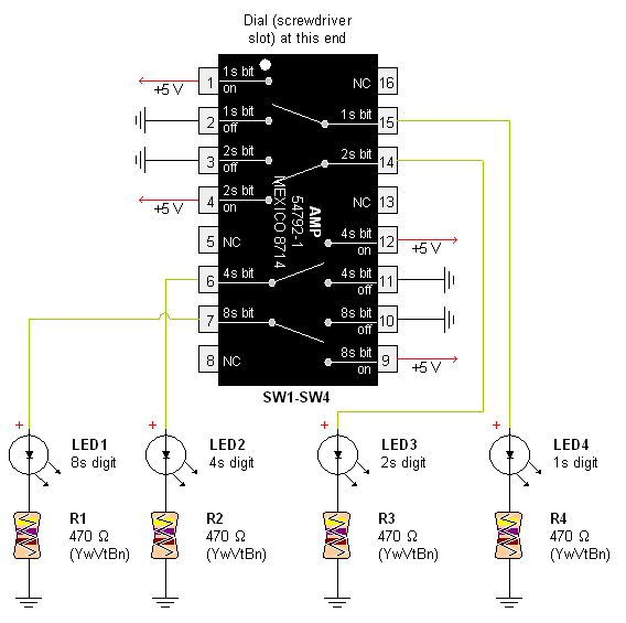
AMP Hexadecimal Rotary Switch
Pictures and a sample schematic (including pinouts) of an AMP hexadecimal (16-position) switch with a screw slot actuator.
The AMP hexadecimal switch is a 16-position rotary switch designed for applications requiring multiple selectable options. This switch features a screw slot actuator...