


Hour time-delay sampling circuit
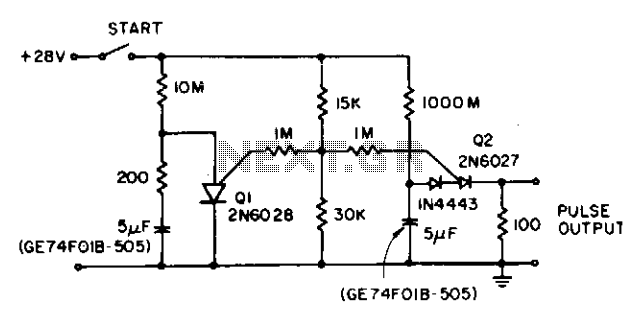
Description: The circuit reduces the effective peak current of the output PUT, Q2. It allows the capacitor to charge with a high gate voltage and periodically lowers the gate voltage. When Q1 fires, the timing resistor can be set to a value that supplies a significantly lower current than IP. The triggering requirement is that there must be a minimum charge to initiate current flow through the timing resistor during the period of the Q1 oscillator. This behavior is not dependent on the size of the capacitor, but rather on the leakage and stability of the capacitor.
The described circuit employs a Programmable Unijunction Transistor (PUT) as the primary output switching device (Q2). The operation of this circuit hinges on the controlled charging and discharging of a capacitor, which is connected to the gate of the PUT. Initially, a high gate voltage is applied, allowing the capacitor to charge rapidly. This charging phase is crucial as it sets the stage for the subsequent operation of the circuit.
Once the capacitor reaches a certain voltage threshold, the gate voltage is periodically reduced. This reduction is essential as it influences the firing of the PUT (Q2). When Q1, which functions as an oscillator, fires, it creates a pulse that allows the timing resistor to regulate the current flowing through the circuit. The value of the timing resistor is critical; it must be chosen such that it limits the current to a level significantly lower than the peak current (IP). This design choice is important for protecting the circuit components from excessive current that could lead to failure.
The triggering mechanism relies on ensuring that the capacitor maintains a minimum charge during the oscillation period of Q1. This minimum charge is necessary to allow current to flow through the timing resistor, thus enabling the circuit to function as intended. The performance of the circuit is influenced not by the size of the capacitor but by its leakage characteristics and stability over time. High leakage can lead to insufficient charge retention, while instability can affect the timing and reliability of the circuit operation.
In summary, this circuit effectively manages the output current through careful control of the capacitor's charging and discharging cycles, utilizing the characteristics of the PUT and the timing resistor to achieve desired operational parameters.The circuit lowers the effective peak current of the output PUT, Q2. By allowing the capacitor to charge with high gate voltage and periodically lowering gate voltage, when Ql fires, the timing resistor can be a value which supplies a much lower current than IP. The triggering requirement here is that minimum charge to trigger flow through the timing resistor during the period of the Ql oscillator.
This is not capacitor size dependent, only capacitor leakage and stability dependent.
The described circuit employs a Programmable Unijunction Transistor (PUT) as the primary output switching device (Q2). The operation of this circuit hinges on the controlled charging and discharging of a capacitor, which is connected to the gate of the PUT. Initially, a high gate voltage is applied, allowing the capacitor to charge rapidly. This charging phase is crucial as it sets the stage for the subsequent operation of the circuit.
Once the capacitor reaches a certain voltage threshold, the gate voltage is periodically reduced. This reduction is essential as it influences the firing of the PUT (Q2). When Q1, which functions as an oscillator, fires, it creates a pulse that allows the timing resistor to regulate the current flowing through the circuit. The value of the timing resistor is critical; it must be chosen such that it limits the current to a level significantly lower than the peak current (IP). This design choice is important for protecting the circuit components from excessive current that could lead to failure.
The triggering mechanism relies on ensuring that the capacitor maintains a minimum charge during the oscillation period of Q1. This minimum charge is necessary to allow current to flow through the timing resistor, thus enabling the circuit to function as intended. The performance of the circuit is influenced not by the size of the capacitor but by its leakage characteristics and stability over time. High leakage can lead to insufficient charge retention, while instability can affect the timing and reliability of the circuit operation.
In summary, this circuit effectively manages the output current through careful control of the capacitor's charging and discharging cycles, utilizing the characteristics of the PUT and the timing resistor to achieve desired operational parameters.The circuit lowers the effective peak current of the output PUT, Q2. By allowing the capacitor to charge with high gate voltage and periodically lowering gate voltage, when Ql fires, the timing resistor can be a value which supplies a much lower current than IP. The triggering requirement here is that minimum charge to trigger flow through the timing resistor during the period of the Ql oscillator.
This is not capacitor size dependent, only capacitor leakage and stability dependent.
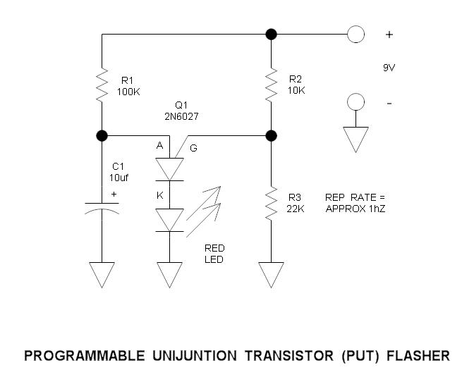
Programmable Unijunction Transistor (PUT) Flasher Circuit
This is a simple circuit that illustrates the function of the programmable unijunction transistor. It can be quickly wired on a proto-board.
The circuit utilizes a programmable unijunction transistor (PUT) to demonstrate its operation as an oscillator. The PUT, which is...
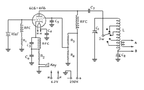
The Ecology of the Oscillator Transmitter
An oscillator-only transmitter appears to be the simplest way to access the radio airwaves; however, it presents several challenges as part of a transmitting and receiving station. The issue of finding an adequate crystal-controlled transmitter for newcomers wishing to operate...
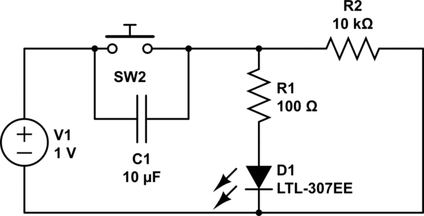
How the capacitor works (in a debouncing circuit)
Understand why the LED does not light up, as the capacitor appears to be bypassing the switch. When the capacitor is fully charged, it does not conduct electricity. Although the individual is a beginner, after 20 hours of studying various...
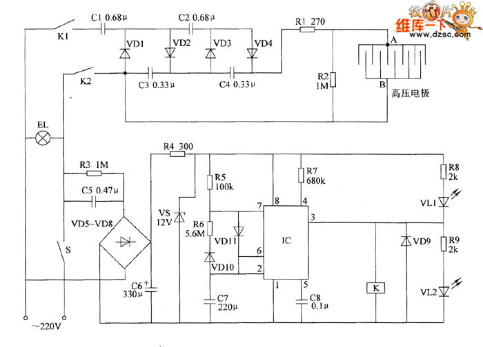
Electronic pests killing lamp circuit diagram 4
The electronic pest-killing lamp circuit comprises an oscillator, control circuit, high voltage generator, LED indicator circuit, and power supply circuit. The schematic diagram illustrates these components. The oscillator circuit includes a time-base integrated circuit (IC), resistors R5 to R7, diodes...
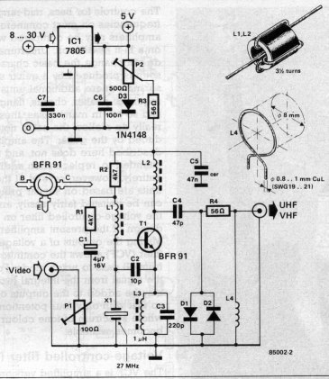
VHF/UHF TV Modulator
A simple oscillator generates a frequency in the VHF or UHF range. This oscillator is modulated with a video signal, and the resulting modulated carrier wave is transmitted to the TV set's aerial input through a cable. The final step...
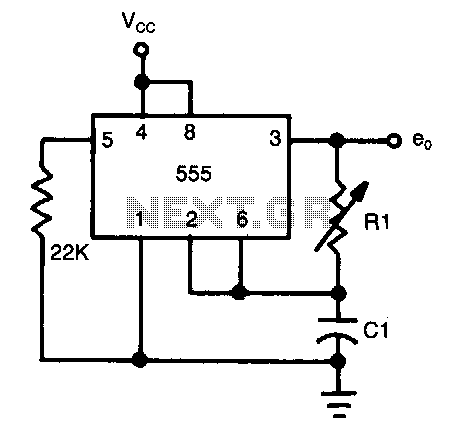
Half-duty-cycle-oscillator
The frequency of oscillation depends on the Rl/Cl time constant, allowing for frequency adjustment by varying Rl. This is a basic circuit.
The described circuit operates based on the relationship between resistance (Rl) and capacitance (Cl), which together form a time...
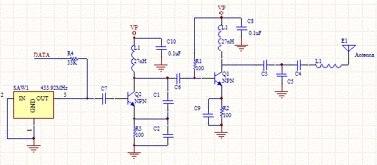
Saw Transmitter Circuit
This circuit utilizes a sawtooth oscillator along with an output amplifier that drives a transistor. The components C1, C2, and L1 are essential for the oscillator's operation, forming a tank circuit that must be tuned to the resonant frequency. Generally,...
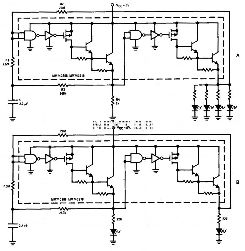
High drive oscillator-flasher
The driver in the package is configured as a Schmitt trigger oscillator (A), utilizing resistors R1 and R2 to create hysteresis. The inverting feedback timing components consist of resistor R3 and capacitor C, while resistor R4 serves as the pull-down...
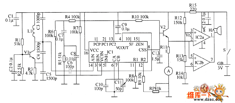
Metal detector circuit diagram 8
The metal detector circuit consists of a probe oscillator, a PLL (phase-locked loop) circuit, and an audio alarm circuit. The probe oscillator includes a detection coil (L), transistor (V1), and several resistors (R1 to R3) and capacitors (C1 to C5)....