


Long delay schematic with CD4040
#CD4040
#binary counter
#Schmitt Trigger
#74HC14
#low frequency oscillator
#long delay
#timer circuit
#squarewave oscillator
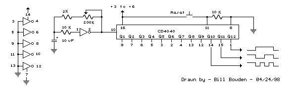
Description: Generating long delays of several hours can be accomplished by using a low frequency oscillator and a binary counter as shown below. A single Schmitt Trigger inverter stage (1/6 of 74HC14) is used as a squarewave oscillator to produce a low frequency of about 0.5 Hertz. The 10K resistor in series with the input (pin 1) reduces the capacitor discharge current through the inverter input internal protection diodes if the circuit is suddenly disconnected from the supply. This resistor may not be needed but is a good idea to use. The frequency is divided by two at each successive stage of the 12 stage binary counter (CD4040) which yields about 1 hour of time before the final stage (Q12) switches to a high state. Longer or shorter times can be obtained by adjusting the oscillator frequency or using different RC values. Each successive stage changes state when the preceding stage switches to a low state (0 volts), thus the frequency at each stage is one half the frequency of the stage before. Waveform diagrams are shown for the last 3 stages. To begin the delay cycle, the counter can be reset to zero by momentarily connecting the reset line (pin 11) to the positive supply. Timing accuracy will not be as good as with a crystal oscillator and may only be around 1 or 2% depending on the stability of the oscillator capacitor.
The circuit described utilizes a low-frequency oscillator and a binary counter to achieve long timing delays, specifically several hours. The oscillator is implemented using a Schmitt Trigger inverter from the 74HC14 series, which generates a square wave output at approximately 0.5 Hz. This frequency is relatively low, making it suitable for extended timing applications. The inclusion of a 10K ohm resistor in series with the input pin of the inverter serves a protective function by limiting the discharge current of the timing capacitor through the internal protection diodes of the inverter, particularly in the event of a sudden power disconnection.
The core of the timing mechanism is a 12-stage binary counter, specifically the CD4040, which divides the input frequency by two at each stage. This division results in a significant reduction in frequency, allowing the final output stage (Q12) to transition to a high state after approximately one hour. The timing duration can be adjusted by modifying the RC time constant in the oscillator circuit or by selecting different resistor and capacitor values, thereby allowing for flexibility in timing applications.
Each stage of the binary counter changes state in response to the preceding stage transitioning to a low voltage (0 volts). Consequently, the frequency output at each stage is half that of the previous stage, leading to a cascading effect that produces the desired long delay. The circuit can be reset to its initial state by momentarily connecting the reset pin (pin 11) to the positive supply voltage, which sets the counter back to zero and restarts the timing cycle.
It is important to note that the timing accuracy of this configuration may not be as precise as that achieved with a crystal oscillator. Variability in timing can occur, potentially resulting in an accuracy of only 1% to 2%, which is influenced by the stability of the oscillator capacitor. This characteristic should be considered when implementing the circuit for applications requiring high timing precision. Overall, this design presents a practical solution for generating long delays in electronic circuits.Generating long delays of several hours can be accomplished by using a low frequency oscillator and a binary counter as shown below. A single Schmitt Trigger inverter stage (1/6 of 74HC14) is used as a squarewave oscillator to produce a low frequency of about 0.5 Hertz.
The 10K resistor in series with the input (pin 1) reduces the capacitor discharge current through the inverter input internal protection diodes if the circuit is suddenly disconnected from the supply. This resistor may not be needed but is a good idea to use. The frequency is divided by two at each successive stage of the 12 stage binary counter (CD4040) which yields about 1 hour of time before the final stage (Q12) switches to a high state. Longer or shorter times can be obtained by adjusting the oscillator frequency or using different RC values.
Each successive stage changes state when the preceding stage switches to a low state (0 volts), thus the frequency at each stage is one half the frequency of the stage before. Waveform diagrams are shown for the last 3 stages. To begin the delay cycle, the counter can be reset to zero by momentarily connecting the reset line (pin 11) to the positive supply.
Timing accuracy will not be as good as with a crystal oscillator and may only be around 1 or 2% depending on the stability of the oscillator capacitor.
The circuit described utilizes a low-frequency oscillator and a binary counter to achieve long timing delays, specifically several hours. The oscillator is implemented using a Schmitt Trigger inverter from the 74HC14 series, which generates a square wave output at approximately 0.5 Hz. This frequency is relatively low, making it suitable for extended timing applications. The inclusion of a 10K ohm resistor in series with the input pin of the inverter serves a protective function by limiting the discharge current of the timing capacitor through the internal protection diodes of the inverter, particularly in the event of a sudden power disconnection.
The core of the timing mechanism is a 12-stage binary counter, specifically the CD4040, which divides the input frequency by two at each stage. This division results in a significant reduction in frequency, allowing the final output stage (Q12) to transition to a high state after approximately one hour. The timing duration can be adjusted by modifying the RC time constant in the oscillator circuit or by selecting different resistor and capacitor values, thereby allowing for flexibility in timing applications.
Each stage of the binary counter changes state in response to the preceding stage transitioning to a low voltage (0 volts). Consequently, the frequency output at each stage is half that of the previous stage, leading to a cascading effect that produces the desired long delay. The circuit can be reset to its initial state by momentarily connecting the reset pin (pin 11) to the positive supply voltage, which sets the counter back to zero and restarts the timing cycle.
It is important to note that the timing accuracy of this configuration may not be as precise as that achieved with a crystal oscillator. Variability in timing can occur, potentially resulting in an accuracy of only 1% to 2%, which is influenced by the stability of the oscillator capacitor. This characteristic should be considered when implementing the circuit for applications requiring high timing precision. Overall, this design presents a practical solution for generating long delays in electronic circuits.Generating long delays of several hours can be accomplished by using a low frequency oscillator and a binary counter as shown below. A single Schmitt Trigger inverter stage (1/6 of 74HC14) is used as a squarewave oscillator to produce a low frequency of about 0.5 Hertz.
The 10K resistor in series with the input (pin 1) reduces the capacitor discharge current through the inverter input internal protection diodes if the circuit is suddenly disconnected from the supply. This resistor may not be needed but is a good idea to use. The frequency is divided by two at each successive stage of the 12 stage binary counter (CD4040) which yields about 1 hour of time before the final stage (Q12) switches to a high state. Longer or shorter times can be obtained by adjusting the oscillator frequency or using different RC values.
Each successive stage changes state when the preceding stage switches to a low state (0 volts), thus the frequency at each stage is one half the frequency of the stage before. Waveform diagrams are shown for the last 3 stages. To begin the delay cycle, the counter can be reset to zero by momentarily connecting the reset line (pin 11) to the positive supply.
Timing accuracy will not be as good as with a crystal oscillator and may only be around 1 or 2% depending on the stability of the oscillator capacitor.
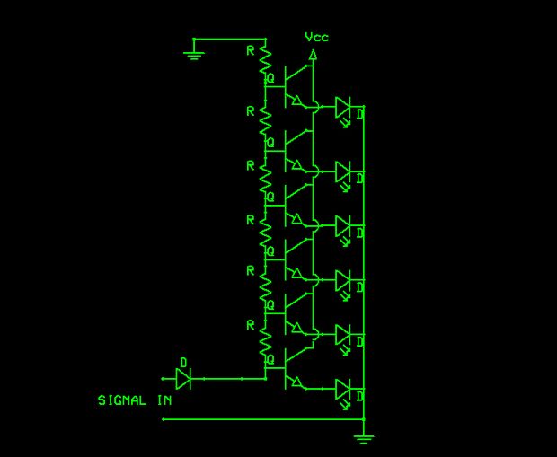
Schmitt Trigger VU Meter
The schematic indicates that the input is routed through a voltage divider. This configuration is essential for the operation of the Schmitt triggers, which all activate under certain conditions.
The voltage divider in the schematic serves to scale down the input...

Schmitt trigger
By replacing the common-emitter resistor in a conventional Schmitt trigger circuit with a Zener diode, the hysteresis typically associated with these circuits is eliminated.
In a conventional Schmitt trigger, the hysteresis is introduced by the feedback mechanism involving the common-emitter resistor,...
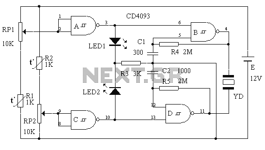
Multi-way pocket alarm circuit
This circuit is a two-way alarm system that utilizes a Schmitt IC, featuring responsive sound and light indicators. It is compact, energy-efficient, and consists of only 13 components, making it a cost-effective solution. The circuit is divided into two sections...
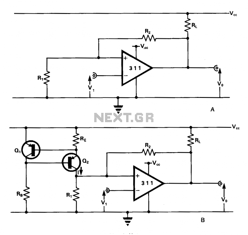
Schmitt trigger comparator
The comparator features an output pull-up resistor (RL) and is configured to function as a Schmitt trigger using a single rail supply (Vcc). The feedback resistors (R1 and R2) establish upper and lower threshold levels (VT+ and VT-), respectively. The...
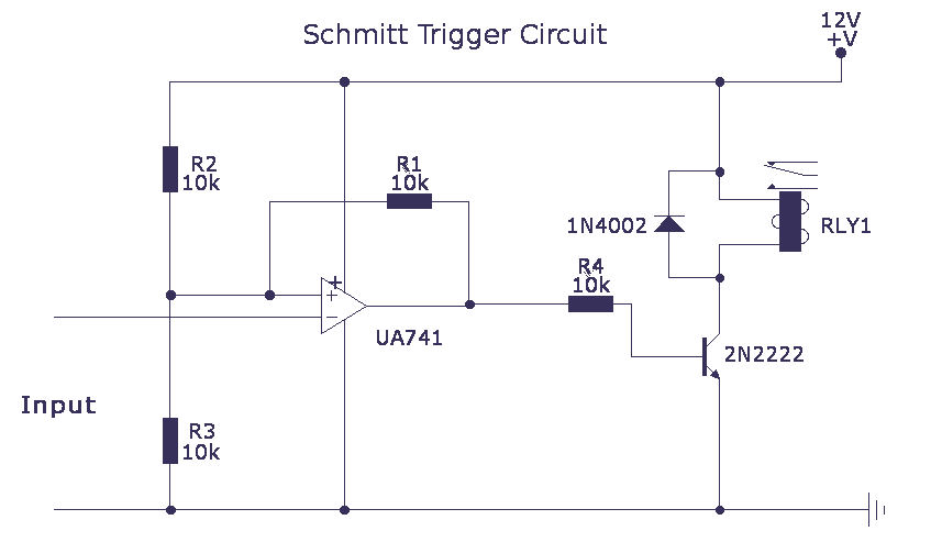
Schmitt trigger with LM741 op-amp
The schmitt trigger circuit is built around a single LM741 op-amp, its output buffered by a transistor, which in turn energizes a relay. The relay may be replaced by a red LED if desired. The LM741 may be replaced by...
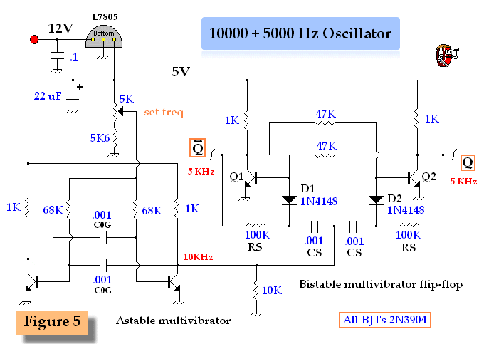
General Hobbyist Circuits
This circuit describes a simple 6-bit random number pseudo-generator used to study binary counters and, in particular, shift registers. Some basic background information about binary counters and shift registers is provided. In reality, there are dozens of different shift register...
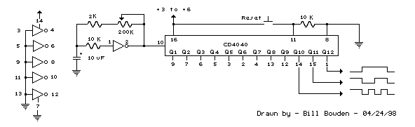
CD4040 Generating Long Time Delays Circuit
Generating long delays of several hours can be achieved using a low-frequency oscillator and a binary counter. A single Schmitt Trigger inverter stage (1/6 of 74HC14) functions as a square wave oscillator, producing a low frequency of approximately 0.5 Hertz....
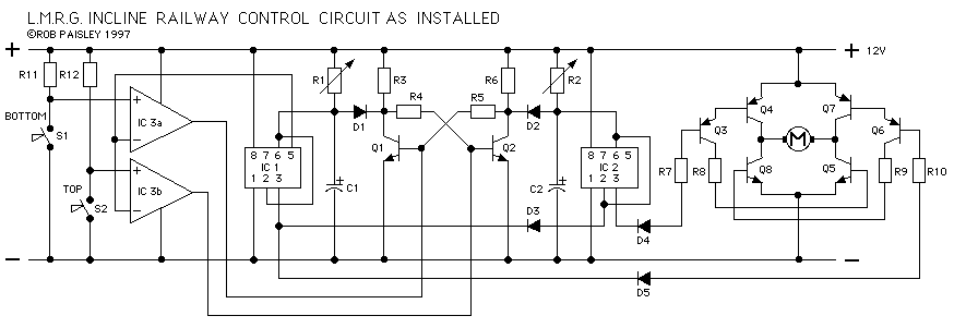
Incline Railway Project
The drawings and photos below are for an operating incline railway that was built by the London Model Railroad Group for its O scale model railway club located at London, Ontario, Canada. This is a single car model loosely based...
Incline Railway Project
The drawings and photos below are for an operating incline railway that was built by the London Model Railroad Group for its O scale model railway club located at London, Ontario, Canada. This is a single car model loosely based...