


Long-Interval Programmable Timer
#programmable timer
#RC oscillator
#ripple counter
#long-interval
#count-rate
#delay circuit
#timing circuit
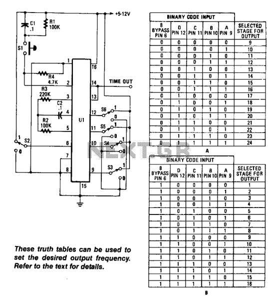
Description: Using an RC oscillator, an up to 24-stage ripple counter (O) 16777216 or 2^24, and a 0.1-Hz count rate, with R2 = 39 kΩ, C2 = 0.001 µF, and R4 = 220 kΩ, the count cycle would take approximately 654 seconds. This example demonstrates the capabilities of this timing circuit, utilizing the Motorola MC14536 timer. A low-frequency oscillator can be employed for extended time periods.
The described circuit employs a resistor-capacitor (RC) oscillator to generate a low-frequency signal suitable for timing applications. The RC oscillator's frequency is determined by the values of the resistors and capacitors in the circuit. In this case, R2 and R4 are configured to establish the timing interval, while C2 provides the necessary capacitance for oscillation. The oscillator output feeds into a 24-stage ripple counter, which is capable of counting up to 16,777,216 (2^24) clock pulses.
The ripple counter operates by incrementing its count with each clock pulse received from the oscillator. At a count rate of 0.1 Hz, the counter will take approximately 654 seconds to complete a full cycle, demonstrating its utility in applications requiring long-duration timing. The MC14536 timer, a versatile integrated circuit, is utilized to manage the timing functions effectively.
For applications requiring even longer time intervals, adjustments to the RC oscillator can be made, such as increasing the resistance or capacitance values, or employing additional stages in the counter. This flexibility allows for the design of timing circuits that can cater to various operational needs, making it a valuable component in digital timing applications across multiple fields. Using an RC oscillator, an up to 24-stage ripple counter O) 16777216 or 2U, and a 0.1-Hz count-rate with # 2 = 39 KOhm, C2 = 0.001 ¥, and R4=220 KOhmhm for example, the count cycle would take about 654 s. This example shows the capabilities of this time circuit, using the Motorola MC14536 timer. A low-frequency oscillator can be used for longer time periods.
The described circuit employs a resistor-capacitor (RC) oscillator to generate a low-frequency signal suitable for timing applications. The RC oscillator's frequency is determined by the values of the resistors and capacitors in the circuit. In this case, R2 and R4 are configured to establish the timing interval, while C2 provides the necessary capacitance for oscillation. The oscillator output feeds into a 24-stage ripple counter, which is capable of counting up to 16,777,216 (2^24) clock pulses.
The ripple counter operates by incrementing its count with each clock pulse received from the oscillator. At a count rate of 0.1 Hz, the counter will take approximately 654 seconds to complete a full cycle, demonstrating its utility in applications requiring long-duration timing. The MC14536 timer, a versatile integrated circuit, is utilized to manage the timing functions effectively.
For applications requiring even longer time intervals, adjustments to the RC oscillator can be made, such as increasing the resistance or capacitance values, or employing additional stages in the counter. This flexibility allows for the design of timing circuits that can cater to various operational needs, making it a valuable component in digital timing applications across multiple fields. Using an RC oscillator, an up to 24-stage ripple counter O) 16777216 or 2U, and a 0.1-Hz count-rate with # 2 = 39 KOhm, C2 = 0.001 ¥, and R4=220 KOhmhm for example, the count cycle would take about 654 s. This example shows the capabilities of this time circuit, using the Motorola MC14536 timer. A low-frequency oscillator can be used for longer time periods.
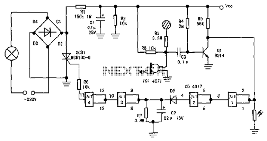
Practical three control delay self-extinguishing switch circuit schematics
The circuit diagram illustrates a sound, light, and touch-controlled delay self-extinguishing switch. It comprises three main sections: the power circuit, the signal conversion detecting circuit, a delay circuit, and a control circuit.
1. Power Circuit: This section consists of diodes...
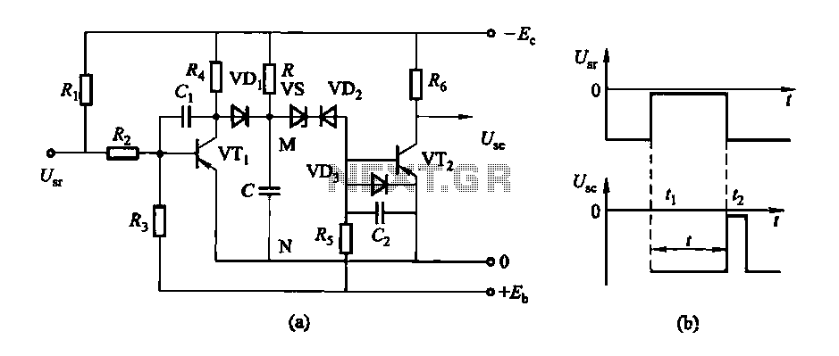
Conducting pipe control rechargeable delay circuit
The circuit features a delay action with an instantaneous reset control mechanism. It is categorized into three types: a conducting pipe rechargeable delay circuit, a tube cut-off control rechargeable delay circuit, and a discharge-type delay circuit. In the conducting pipe...
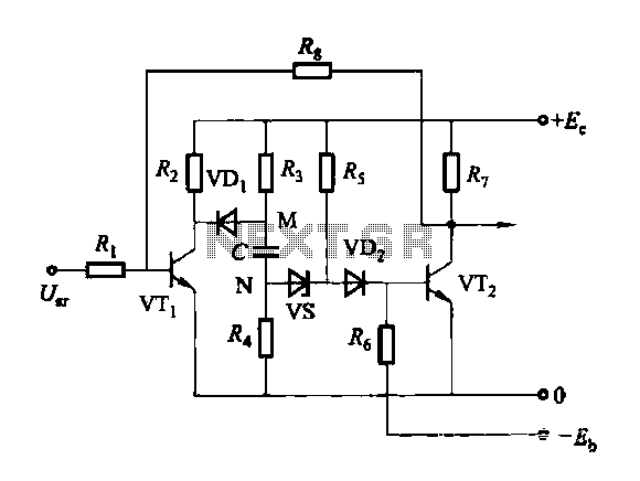
Discharge before memory circuit
Discharge before memory circuit. Before the memory circuit is activated, a delay reset circuit is required. When the input signal triggers an action, timing begins, and after a specified delay, the circuit reverts to its original state. During this interval,...
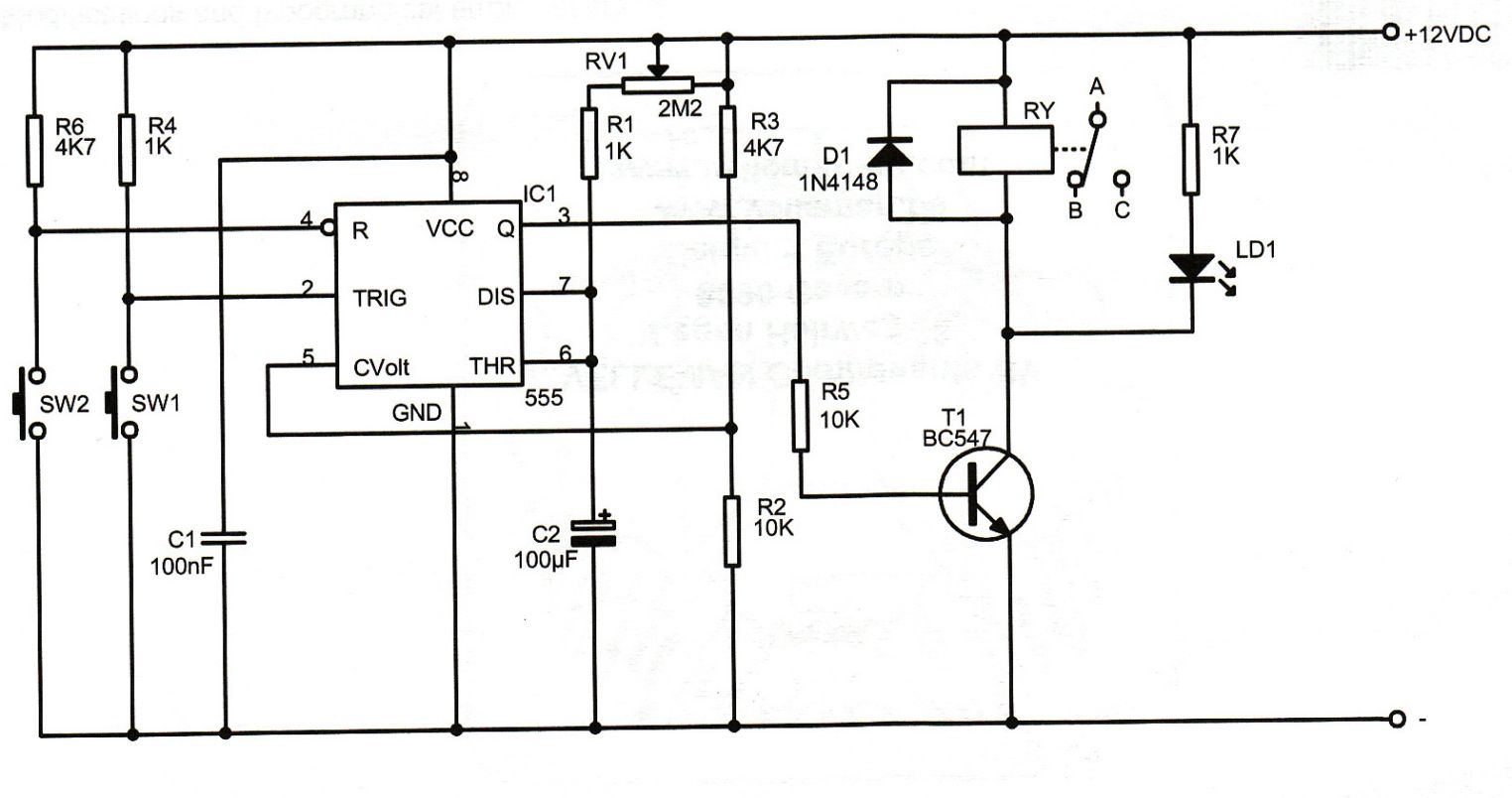
12v 10 minute Off-Delay timer
An Xbox 360 console previously experienced a problem known as the 3 Red Lights of Death (3RLOD). To address this issue, the stock heatsinks were removed, and a Koolance external water cooling system was installed. This modification has effectively resolved...
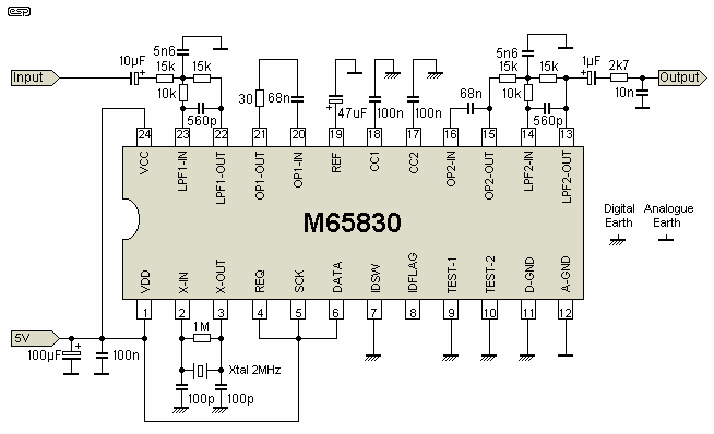
The Delay
The delay circuit utilizes the Mitsubishi M65830 Digital Delay chip, as illustrated in Figure 1. This chip has been in use for some time and is known for its simplicity and effectiveness, particularly when a fixed delay is sufficient. However,...
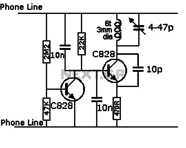
delay circuit for surround sound
This circuit utilizes the Mitsubishi M65830 Digital Delay chip, which has proven to be simple and effective for applications requiring a fixed delay. The serial data necessary for achieving various delay settings is not readily available and would significantly increase...
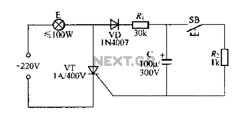
Simple delay lamp circuit 1
Figure 57 illustrates a simple delay lamp circuit that connects to lamp E using a two-wire connection. This design allows for the security bars to be installed directly, enabling replacement with a standard wall switch without altering the existing interior...
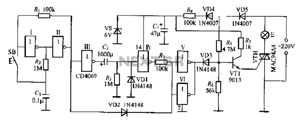
Digital delay circuit lamp circuit 3
A delay lamp circuit is ideal for bedside tables, featuring a button (SB) that turns the light on and off. If the button is not pressed, the circuit maintains a delay before the light turns off. If the light turns...
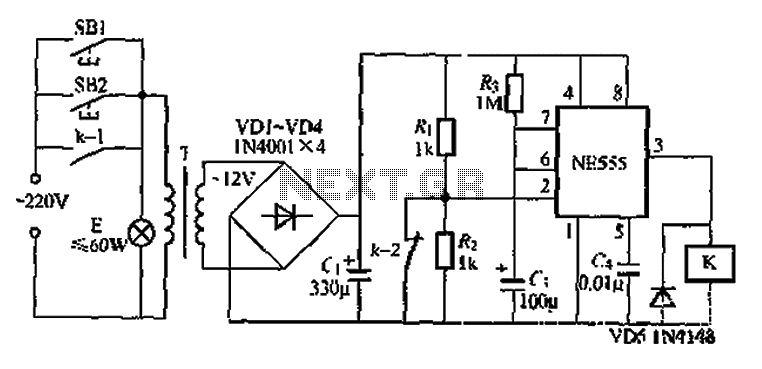
When using the lamp base circuit delay circuit 2
Another application involves the use of a NE555 delay lamp circuit, where components SB1 and SH2 act as J-light buttons that can be installed in two different locations. The lamp can be activated by pressing either SB1 or SB2, which...