


Long-time-timer
#ZN1034E
#Ferranti
#timer
#delay
#oscillator
#binary counter
#voltage regulator
#control logic
#timed intervals
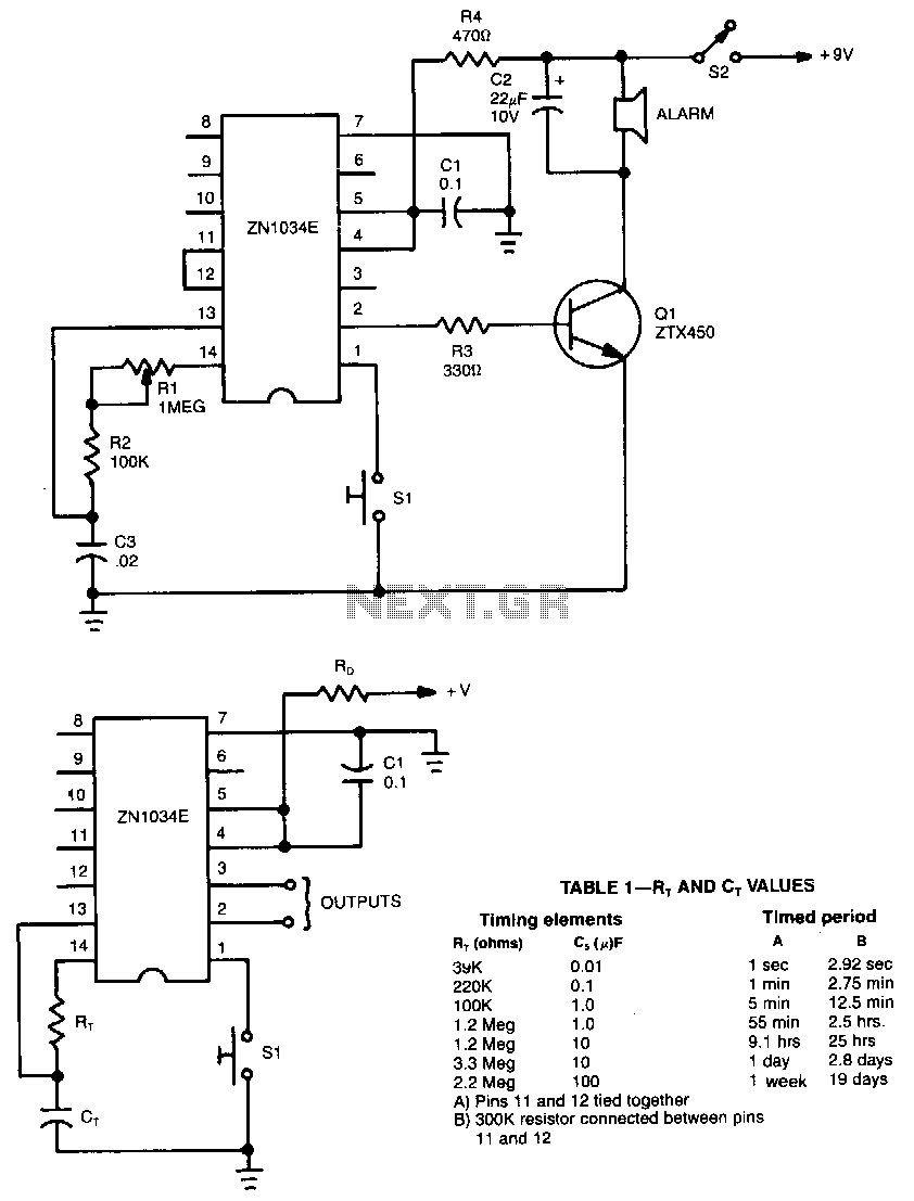
Description: When used as a stand-alone device, the ZN1034E from Ferranti can provide timed intervals ranging from 1 second to 19 days, although the RC time constant is only 220 seconds. The ZN1034E includes an internal voltage regulator, an oscillator, and a 12-stage binary counter. The total delay time provided by the counter is 4095 times the oscillator period. The control logic times out after 4095 cycles of the oscillator and delivers high and low output pulses at pins 2 and 3. The output at pin 3 is normally high and decreases at the end of the timed interval. The complementary output at pin 2 is normally low and becomes high at the end of the timed interval. The timing period is initiated by momentarily grounding pin 1. The timing resistor R7 consists of two resistors, R1 and R2, in series. Because R1 has a fixed value of 100 kΩ, the total range of R7 is from 100 kΩ to 1.1 MΩ.
The ZN1034E timer circuit is designed for applications requiring precise timing intervals over an extensive range. The internal voltage regulator ensures stable operation by maintaining a consistent voltage supply, which is crucial for accurate timing. The oscillator generates clock pulses that drive the 12-stage binary counter, allowing for a maximum timing duration that can be calculated as 4095 times the oscillator period. This provides flexibility in applications where varying timing intervals are needed.
The outputs at pins 2 and 3 serve distinct functions. Pin 3 provides a high output during the timing period, transitioning to low at the conclusion of the set interval, which can be utilized to trigger subsequent actions in a circuit. Conversely, pin 2 operates in a complementary manner, remaining low throughout the timing period and switching high at the end, making it suitable for signaling purposes or as an enable signal for other components.
The initiation of the timing cycle is accomplished by grounding pin 1, which activates the timing sequence. The timing resistor R7, composed of R1 and R2 in series, allows for fine-tuning of the timing interval. With R1 fixed at 100 kΩ, the variable resistor R2 can be adjusted to achieve a total resistance range from 100 kΩ to 1.1 MΩ. This adjustability is critical for tailoring the timing characteristics to meet specific application requirements, whether for short delays or extended timing sequences.
Overall, the ZN1034E is a versatile and reliable timing device suitable for a wide range of electronic applications, providing both high precision and flexibility in timing control.When used as a stand-alone device, ZN1034E from Ferranti can provide timed intervals ranging from 1 second to 19 days, although the rc time constant is only 220 seconds. The ZN1034E includes an internal voltage regulator, an oscillator, and a 12-stage binary counter. The total delay time provided by the counter is 4095 times the oscillator period. The control logic times-out after 4095 cyCles of the oscillator, and delivers high and low output pulses at pins 2 and 3.
The output at pin 3 is normally high and decreases at the end of the timed interval. The complementary output at pin 2 is normally low and becomes high at tbe end of the timed interval. The timing period is initiated by momentarily grounding pin 1. Timing resistor R 7 consists of two resistors, R1 and R2, in series. Because R1 has a fixed value of 100 KO, the total range of R7 is 100 K to 1.1 MO.
The ZN1034E timer circuit is designed for applications requiring precise timing intervals over an extensive range. The internal voltage regulator ensures stable operation by maintaining a consistent voltage supply, which is crucial for accurate timing. The oscillator generates clock pulses that drive the 12-stage binary counter, allowing for a maximum timing duration that can be calculated as 4095 times the oscillator period. This provides flexibility in applications where varying timing intervals are needed.
The outputs at pins 2 and 3 serve distinct functions. Pin 3 provides a high output during the timing period, transitioning to low at the conclusion of the set interval, which can be utilized to trigger subsequent actions in a circuit. Conversely, pin 2 operates in a complementary manner, remaining low throughout the timing period and switching high at the end, making it suitable for signaling purposes or as an enable signal for other components.
The initiation of the timing cycle is accomplished by grounding pin 1, which activates the timing sequence. The timing resistor R7, composed of R1 and R2 in series, allows for fine-tuning of the timing interval. With R1 fixed at 100 kΩ, the variable resistor R2 can be adjusted to achieve a total resistance range from 100 kΩ to 1.1 MΩ. This adjustability is critical for tailoring the timing characteristics to meet specific application requirements, whether for short delays or extended timing sequences.
Overall, the ZN1034E is a versatile and reliable timing device suitable for a wide range of electronic applications, providing both high precision and flexibility in timing control.When used as a stand-alone device, ZN1034E from Ferranti can provide timed intervals ranging from 1 second to 19 days, although the rc time constant is only 220 seconds. The ZN1034E includes an internal voltage regulator, an oscillator, and a 12-stage binary counter. The total delay time provided by the counter is 4095 times the oscillator period. The control logic times-out after 4095 cyCles of the oscillator, and delivers high and low output pulses at pins 2 and 3.
The output at pin 3 is normally high and decreases at the end of the timed interval. The complementary output at pin 2 is normally low and becomes high at tbe end of the timed interval. The timing period is initiated by momentarily grounding pin 1. Timing resistor R 7 consists of two resistors, R1 and R2, in series. Because R1 has a fixed value of 100 KO, the total range of R7 is 100 K to 1.1 MO.
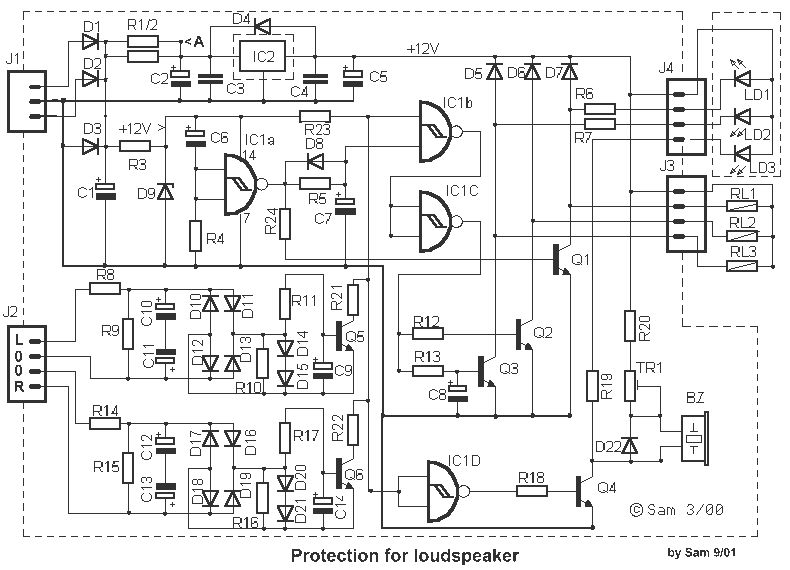
Delay switching for Loudspeaker
The supply of circuit becomes from a AC line in the J1. This voltage can be from a separate transformer 2X12V (the prices of materials that I give it is for 2X12V AC), from existing coil 12V in their M/T...
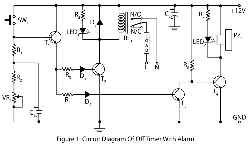
Off timer with alarm with description
An off timer with an alarm is a straightforward project designed to indicate the end of a specified time period. The circuit utilizes four transistors. It includes a circuit diagram along with a parts list and a description of the...
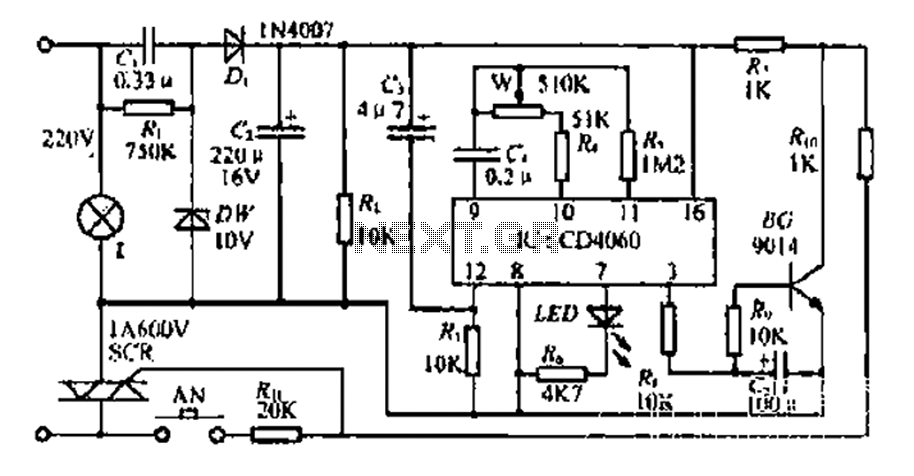
A bedside lamp delay circuit
The circuit includes a CD4 component with a connection of 16 feet for the Vcc terminal, 8 feet for the ground, 12 feet for the reset terminal, 7 feet for the Qt end, and 3 feet for the Q end....
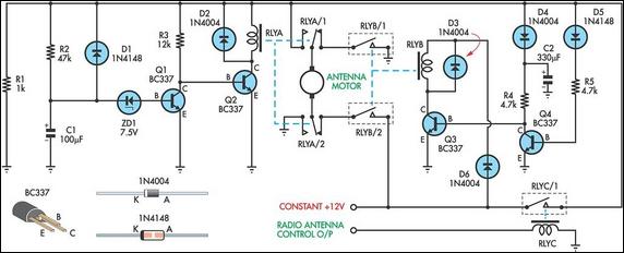
Up/Down Timer For A Power Antenna
This up/down timer was designed to control a power antenna on a late-model vehicle. Normally, this vehicle uses a body computer to control the antenna. However, the owner intended to install a high-powered audio stereo system. The original stereo system...
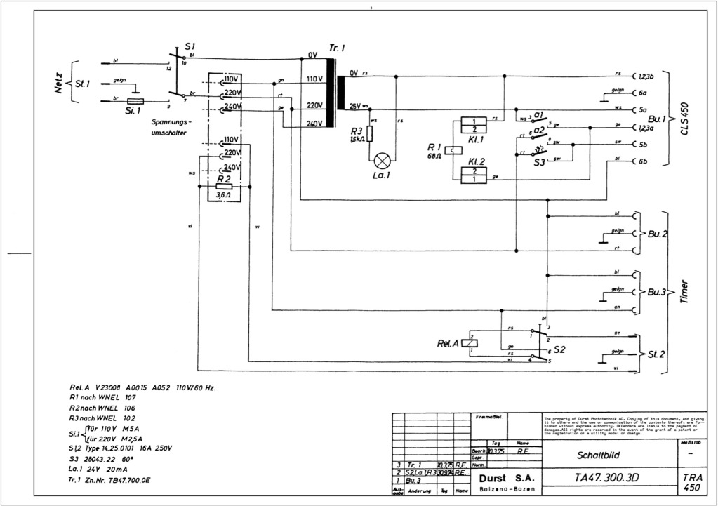
Durst power supplies EST 301 and EST 450
The regulator board of the ES301 has been inspected, revealing that the PCB contacts of the current sensing resistors R42 and R43 are severely burned. There is a nearby group of resistors that also need to be replaced, but their...
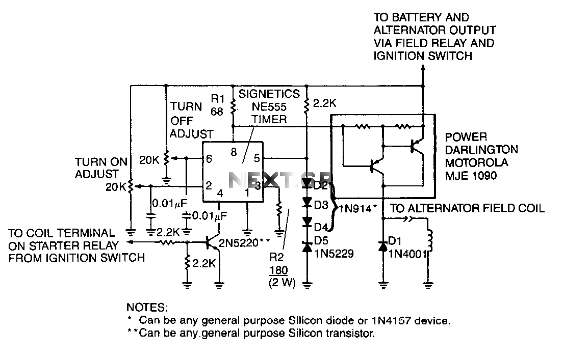
Automobile-voltage-regulator
A monolithic 555-type timer serves as the core component of this straightforward automobile voltage regulator. When the timer is inactive, resulting in a low output at pin 3, the power Darlington transistor pair remains off. If the battery voltage drops...
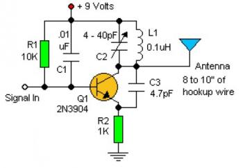
Basic RF Oscillator circuit diagram
Experimenting with the size of the coil and the number of turns can influence the frequency and signal output of the oscillator. The signal can be received using a standard FM radio receiver. The input signal should be coupled via...
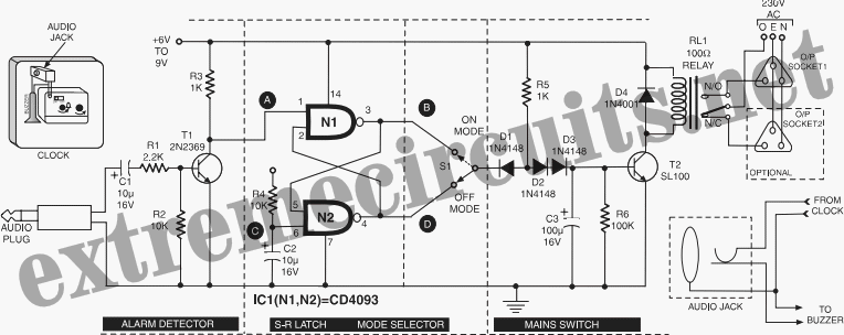
Time Switch
This circuit is specifically designed for individuals who frequently need to wake up early in the morning. Standard alarms in electronic watches are often insufficiently loud.
The circuit utilizes a high-decibel audio output mechanism to ensure that the alarm is audible...
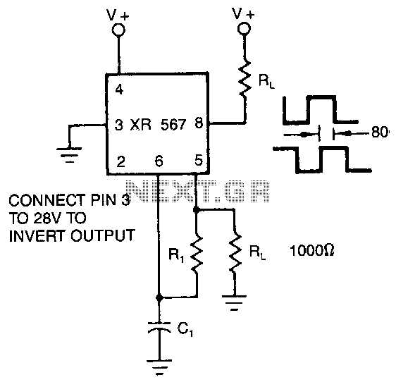
Quadrature-outputs-oscillator
The XR-567 operates as a precision oscillator, providing two distinct square-wave outputs at pins 5 and 8, which are nearly in quadrature phase with one another. Due to the internal biasing configuration, the typical phase shift between the two outputs...