


Mains-Powered Timer
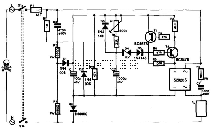
Description: This timer can be integrated into a power line to provide a controllable delay before a load is activated. The mains voltage is reduced by capacitor C3 and rectified to yield approximately 30 V across capacitor C1. This voltage charges capacitor C2 gradually through resistor R4 and potentiometer P1. When the voltage across C2 reaches about 14 V, the electronic switch formed by transistors T1 and T2 activates a solid-state relay (Sharp S202DS). When the mains voltage is disconnected, C2 discharges rapidly through diode D6 and resistor R10. The delay can be adjusted from 15 seconds (with P1 set to minimum resistance) to 5 minutes (with P1 set to maximum resistance). The solid-state relay requires adequate cooling based on the current drawn by the load: no heatsink is necessary for loads up to 1 A, while a heatsink of at least 55 cm is recommended for loads between 1 A and the maximum of 3 A. Safety considerations are critical during circuit assembly, as many components will be at mains potential. For instance, housing the unit in an ABS or other synthetic enclosure is essential. If a potentiometer is utilized for P1, its shaft must be insulated. If a preset potentiometer is employed, it should not be accessible through an opening in the enclosure. Switch S1 is a double-pole, single-throw (DPST) switch that disconnects the circuit from the mains. However, the only safe method to work on the circuit is to unplug the mains socket and allow sufficient time for C3 to discharge.
This timer circuit is designed to introduce a controlled delay in powering a load, making it suitable for applications where a timed activation is necessary. The circuit begins with the reduction of mains voltage through capacitor C3, which is subsequently rectified to approximately 30 V at capacitor C1. This rectified voltage serves to charge capacitor C2 through the combination of resistor R4 and potentiometer P1, allowing for user-adjustable timing.
The charging process of capacitor C2 is critical as it determines when the electronic switch, composed of transistors T1 and T2, will activate the solid-state relay (SSR). The relay, specifically the Sharp S202DS, is responsible for energizing the load once the voltage across C2 exceeds 14 V. This design choice ensures that the load is only powered after the desired delay period, which can be finely adjusted between 15 seconds and 5 minutes based on the settings of potentiometer P1.
Upon disconnection from the mains, capacitor C2 discharges rapidly through diode D6 and resistor R10, ensuring a quick reset of the timing mechanism for the next cycle. The thermal management of the solid-state relay is also a crucial aspect of this design. With loads up to 1 A, the relay can operate without additional cooling, but for higher loads, a heatsink is necessary to prevent overheating and potential failure.
Safety is paramount when working with this circuit due to the presence of mains voltage. The enclosure should be constructed from non-conductive materials such as ABS to prevent accidental electric shocks. If a potentiometer is used for timing adjustments, it is imperative that its shaft is insulated to avoid any risk of electric shock. Additionally, if a preset potentiometer is chosen instead, it must be configured such that it is not accessible through any openings in the enclosure, further enhancing safety.
The circuit includes a DPST switch, S1, which disconnects the entire circuit from the mains supply. However, it is important to note that to work safely on the circuit, the mains plug must be removed from the socket, and adequate time must be allowed for capacitor C3 to discharge fully, ensuring that all components are safe to handle. This comprehensive attention to detail in both functionality and safety makes this timer circuit a reliable choice for controlled load activation in various applications. This timer can be inserted in a power line to provide a controllable delay before a load is energized. The mains voltag e is reduced by C3 and rectified to give about 30 V across CI. This potential charges C2 slowly via R4/P1. When UC2 reaches about 14 V, electronic switch T1/T2 actuates a solid-state relay (a Sharp S202DS). When the mains voltage is removed, C2 discharges rapidly via D6 and RIO. The delay extends from 15 s (PI set to minimum resistance) to 5 min (PI set to maximum resistance). The solid-state relay needs cooling in accordance with the current drawn by the load: at up to 1 A, no heatsink is required; at 1 to 3 A (max), a 55 cm heatsink is advisable. During the building of the circuit, consideration must be given to safety because many parts will be at mains potential.
For instance, fitting the unit in an ABS or other man-made fiber enclosure is a must. If a potentiometer is used for PI, its spindle should be insulated. If a preset is used, it must not be accessible through a hole in the enclosure. Switch SI is a DPST that disconnects the circuit from the mains. Nevertheless, the only way to safely work on the circuit is to unplug the mains socket and allow C3 sufficient discharge time.
This timer circuit is designed to introduce a controlled delay in powering a load, making it suitable for applications where a timed activation is necessary. The circuit begins with the reduction of mains voltage through capacitor C3, which is subsequently rectified to approximately 30 V at capacitor C1. This rectified voltage serves to charge capacitor C2 through the combination of resistor R4 and potentiometer P1, allowing for user-adjustable timing.
The charging process of capacitor C2 is critical as it determines when the electronic switch, composed of transistors T1 and T2, will activate the solid-state relay (SSR). The relay, specifically the Sharp S202DS, is responsible for energizing the load once the voltage across C2 exceeds 14 V. This design choice ensures that the load is only powered after the desired delay period, which can be finely adjusted between 15 seconds and 5 minutes based on the settings of potentiometer P1.
Upon disconnection from the mains, capacitor C2 discharges rapidly through diode D6 and resistor R10, ensuring a quick reset of the timing mechanism for the next cycle. The thermal management of the solid-state relay is also a crucial aspect of this design. With loads up to 1 A, the relay can operate without additional cooling, but for higher loads, a heatsink is necessary to prevent overheating and potential failure.
Safety is paramount when working with this circuit due to the presence of mains voltage. The enclosure should be constructed from non-conductive materials such as ABS to prevent accidental electric shocks. If a potentiometer is used for timing adjustments, it is imperative that its shaft is insulated to avoid any risk of electric shock. Additionally, if a preset potentiometer is chosen instead, it must be configured such that it is not accessible through any openings in the enclosure, further enhancing safety.
The circuit includes a DPST switch, S1, which disconnects the entire circuit from the mains supply. However, it is important to note that to work safely on the circuit, the mains plug must be removed from the socket, and adequate time must be allowed for capacitor C3 to discharge fully, ensuring that all components are safe to handle. This comprehensive attention to detail in both functionality and safety makes this timer circuit a reliable choice for controlled load activation in various applications. This timer can be inserted in a power line to provide a controllable delay before a load is energized. The mains voltag e is reduced by C3 and rectified to give about 30 V across CI. This potential charges C2 slowly via R4/P1. When UC2 reaches about 14 V, electronic switch T1/T2 actuates a solid-state relay (a Sharp S202DS). When the mains voltage is removed, C2 discharges rapidly via D6 and RIO. The delay extends from 15 s (PI set to minimum resistance) to 5 min (PI set to maximum resistance). The solid-state relay needs cooling in accordance with the current drawn by the load: at up to 1 A, no heatsink is required; at 1 to 3 A (max), a 55 cm heatsink is advisable. During the building of the circuit, consideration must be given to safety because many parts will be at mains potential.
For instance, fitting the unit in an ABS or other man-made fiber enclosure is a must. If a potentiometer is used for PI, its spindle should be insulated. If a preset is used, it must not be accessible through a hole in the enclosure. Switch SI is a DPST that disconnects the circuit from the mains. Nevertheless, the only way to safely work on the circuit is to unplug the mains socket and allow C3 sufficient discharge time.
Long Delay TimerCircuit
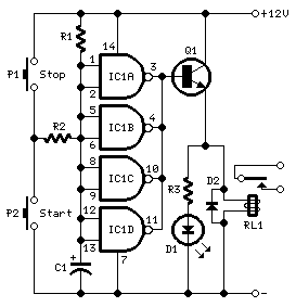
This timer was designed primarily to switch off a portable radio after a set period. This feature allows users to fall asleep on the beach or in a hammock, knowing that the receiver will automatically turn off after a specified...
Delayed start for mains equipment
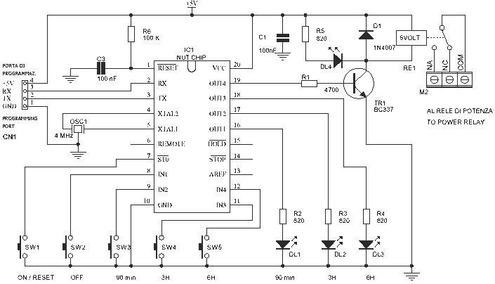
The schematic requires few components because the timer function has been incorporated by Nutchip. For once, from the start, made up of contacts of the relay RE1 connected to terminal M2. If we turn on an appliance at the end...
Using the MCU Timers
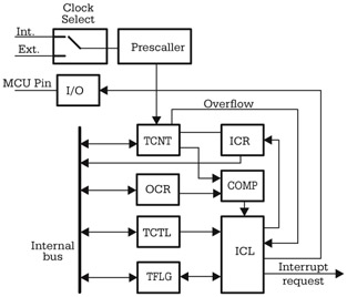
Although there are significant variations between different implementations of the general-purpose timer in various microcontrollers, many similarities exist in the principles of operation and the structure of the timer subsystem. The central element of the timer subsystem is a counter,...
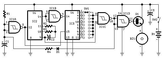
Jogging Timers
This circuit was developed in response to requests from visitors of this website for a timer that can emit a beep after one, two, three minutes, and so on, for jogging purposes. As illustrated in the circuit diagram, SW1 is...
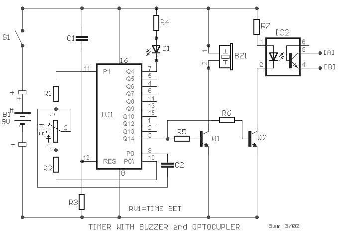
Timer with buzzer and optocoupler circuit
A small circuit designed for various time measurement applications. It features an audible sound signal from the buzzer BZ1 and has the capability to drive an external circuit through the optocoupler IC2, once the appropriate circuit is connected to contacts...
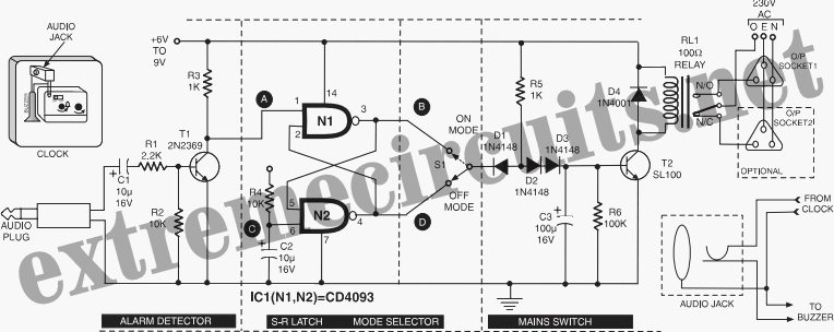
Time Switch
This circuit is specifically designed for individuals who frequently need to wake up early in the morning. Standard alarms in electronic watches are often insufficiently loud and frequently fail to wake users. The switch circuit described here will be useful;...
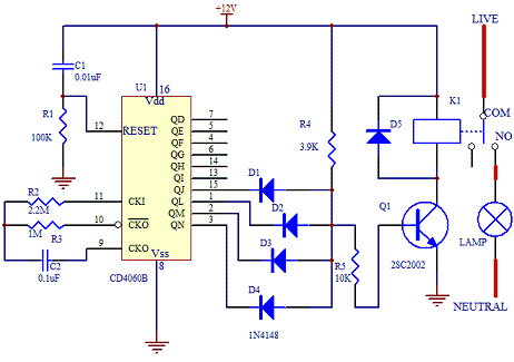
Electronic Timer Switch
This electronic timer switch will turn on a light for 100 seconds, turn it off for another 100 seconds, and then turn it on again for 100 seconds after an hour of powering up the circuit. It is a good...
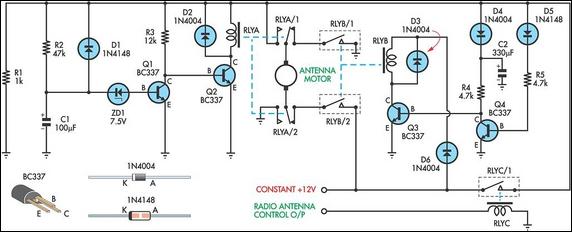
Up/Down Timer For A Power Antenna
This up/down timer was designed to control a power antenna on a late-model vehicle. Normally, this vehicle uses a body computer to control the antenna. However, the owner intended to install a high-powered audio stereo system. The original stereo system...
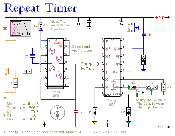
A Regularly Repeating Interval Timer circuit
This circuit features an adjustable output timer capable of re-triggering at regular intervals. The output duration can range from a fraction of a second to over half an hour, and it can be configured to recur at regular intervals from...