


Photo-Event Timer

Description: S2 is utilized to initiate timing. A transition from light to dark or dark to light halts this timer, depending on the configuration of S5. S3 provides a direct operating mode, bypassing the latch. IC3 and IC4 generate timing pulses of either 0.1 seconds or 1 second. IC7 powers a time display counter, which operates at 12 Vdc and consumes less than 200 mA.
The circuit described involves several components that work together to create a timing system with specific operational modes. The switch S2 serves as the primary control element, initiating the timing sequence. The functionality of S2 is complemented by switch S5, which determines the conditions under which the timer stops—either a transition from light to dark or from dark to light.
S3 introduces an alternative mode of operation, allowing the circuit to function without the need for a latch. This direct operating mode can simplify the timing process, enabling immediate response to S2's activation.
Timing pulses are generated by integrated circuits IC3 and IC4, which can be configured to provide either 0.1-second or 1-second intervals. This flexibility in timing pulse generation allows for various applications depending on the requirements of the overall system.
IC7 is responsible for driving a time display counter, which operates at a voltage of 12 Vdc. This counter is designed to be energy-efficient, drawing less than 200 mA, making it suitable for battery-operated or low-power applications. The design considerations for IC7 ensure that the display remains functional without excessive power consumption, contributing to the overall efficiency of the timing circuit.
This combination of components and their specific roles creates a versatile timing system that can be adapted for different uses, whether in industrial applications, consumer electronics, or educational projects. The careful selection of components and their configurations allows for reliable operation under varying conditions. S2 is used to initiate timing. A light-to-dark or dark-to-light transition stops this timer, depending on the setting of S5. S3 offers a direct operating mode, rather than through the latch. IC3 and IC4 supply 0.1- or 1-second timing pulses. IC7 drives a time display counter, a 12-Vdc unit that draws less than 200 mA.
The circuit described involves several components that work together to create a timing system with specific operational modes. The switch S2 serves as the primary control element, initiating the timing sequence. The functionality of S2 is complemented by switch S5, which determines the conditions under which the timer stops—either a transition from light to dark or from dark to light.
S3 introduces an alternative mode of operation, allowing the circuit to function without the need for a latch. This direct operating mode can simplify the timing process, enabling immediate response to S2's activation.
Timing pulses are generated by integrated circuits IC3 and IC4, which can be configured to provide either 0.1-second or 1-second intervals. This flexibility in timing pulse generation allows for various applications depending on the requirements of the overall system.
IC7 is responsible for driving a time display counter, which operates at a voltage of 12 Vdc. This counter is designed to be energy-efficient, drawing less than 200 mA, making it suitable for battery-operated or low-power applications. The design considerations for IC7 ensure that the display remains functional without excessive power consumption, contributing to the overall efficiency of the timing circuit.
This combination of components and their specific roles creates a versatile timing system that can be adapted for different uses, whether in industrial applications, consumer electronics, or educational projects. The careful selection of components and their configurations allows for reliable operation under varying conditions. S2 is used to initiate timing. A light-to-dark or dark-to-light transition stops this timer, depending on the setting of S5. S3 offers a direct operating mode, rather than through the latch. IC3 and IC4 supply 0.1- or 1-second timing pulses. IC7 drives a time display counter, a 12-Vdc unit that draws less than 200 mA.
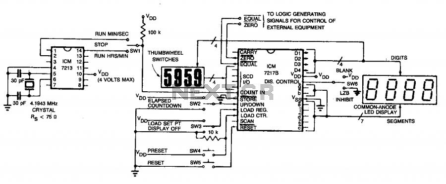
Precision time-countdown timer
The circuit employs an ICM7213 precision timebase generator with a frequency of 4.1943 MHz, which is utilized for generating pulses that are counted by an ICM7217B counter. Thumbwheel switches are incorporated to allow the user to input a starting time...
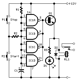
long delay timer circuit diagram
This timer was designed primarily to turn off a portable radio after a specific duration. This feature allows users to fall asleep on the beach or in a hammock, with the assurance that the radio will automatically shut off after...
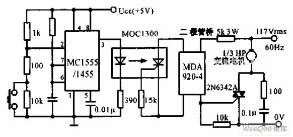
The switch shut off time delay circuit diagram
The switch shut-off time delay circuit consists of a timer, optocouplers, a bridge SCR, and an SCR AC switch. When the control button is released, it allows the motor or other AC power to remain active for one hour. Upon...
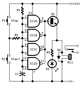
long delay timer schematics
This timer is designed to automatically switch off a portable radio after a set period, allowing users to relax without worrying about battery drain. Resistor R1 and capacitor C1 create a long time constant. When switch P2 is momentarily closed,...
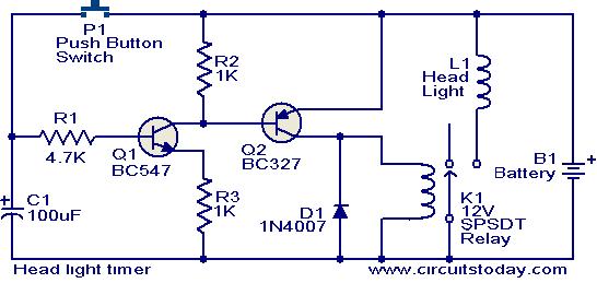
Head light timer circuit
This circuit is a compact timer that keeps the headlights of a car on for approximately 1.5 minutes before turning them off. Incorporating this circuit into a vehicle allows access to dark areas without the need to return and manually...
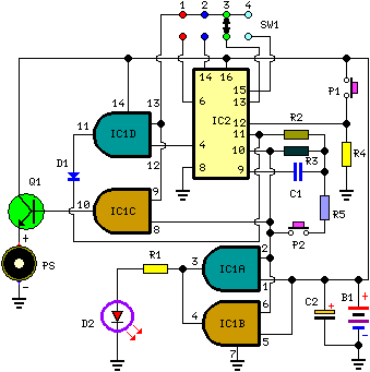
A Very Useful Timed Beeper Circuit Schematic
This circuit is designed to provide alerts after a predetermined time interval. It is ideal for tabletop games that necessitate a fixed duration for answering questions or moving pieces. In this context, it serves as a contemporary alternative to the...
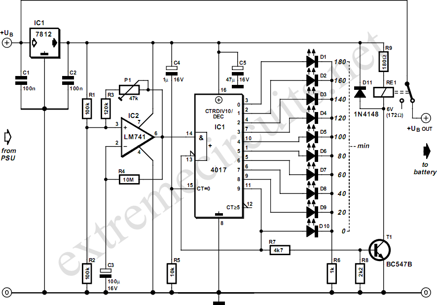
Three Hour Timer
Manufacturers of cordless drills typically recommend a battery charging time of three hours. Once this charging time is complete, the battery must be disconnected from the charger to prevent the risk of overcharging. This circuit, positioned between the charger and...
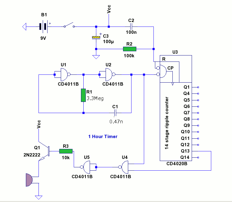
1 Hour Timer
Speaker relay delay controlling circuit for audio amplifier
The speaker relay delay control circuit is designed to protect audio amplifiers and speakers from potential damage caused by inrush current or transient signals during power-up or power-down sequences. This circuit typically employs...
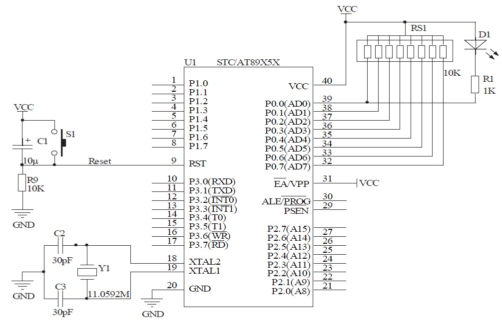
Timing within the one-chip computer Counter and interrupt system
This document will present an overview of two critical components within a one-chip computer: the timing/counter system and the interrupt system. Through this explanation, readers will gain insight into the operating principles of these systems. For illustration, consider an alarm...