


Programmable Timer For Long Intervals
#programmable timer
#RC oscillator
#long interval
#counter
#divider
#timing circuit
#delay circuit
#electronics project
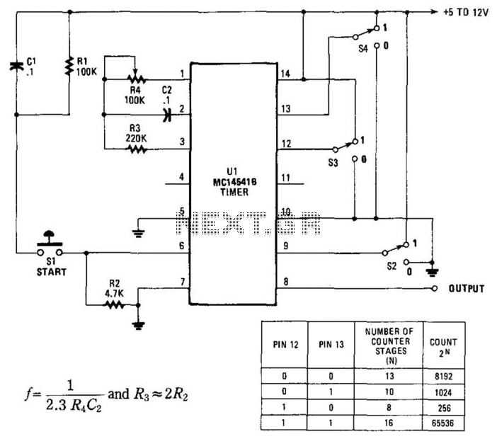
Description: By utilizing an RC oscillator and a programmable divider, this counter can operate for extended periods. The interval oscillator functions at a frequency determined by specific component values: for instance, with R1 = 390 kΩ and C2 = 10 µF, the oscillator can achieve a frequency of 0.1 Hz. When this frequency is divided by 65536, it results in a cycle duration of approximately 655,000 seconds (or 182 hours, which is slightly more than a week). The inputs at pins 12 and 13 of the MC14415 programmable counter specify the number of counter stages selected, thereby influencing the total count.
The described circuit employs a resistor-capacitor (RC) oscillator, which is a fundamental building block in timing applications. The frequency of oscillation is determined by the values of the resistor (R1) and the capacitor (C2). In this case, a resistor value of 390 kΩ and a capacitor value of 10 µF yield a low frequency of 0.1 Hz. This low frequency is suitable for applications requiring long time intervals, such as timers or counters that need to operate over extended durations without frequent resets.
The MC14415 programmable counter is employed to divide the frequency output from the RC oscillator. The division factor of 65536 is significant, as it allows for a long counting period, resulting in a total cycle time of approximately 655,000 seconds. This feature is particularly useful in applications that require precise timing over days or weeks.
The programmable counter's inputs at pins 12 and 13 are critical for selecting the number of stages in the counting process. By configuring these pins, users can tailor the counter's operation to meet specific needs, allowing for flexibility in design. The ability to program different counting stages enables the circuit to adapt to various timing requirements, making it suitable for a broad range of applications in electronics, including timers, clocks, and event counters.
Overall, this circuit design exemplifies the integration of an RC oscillator with a programmable counter to achieve extended counting capabilities, illustrating a practical approach to time-based electronic applications. By using an RC oscillator and a programmable divider, this counter can run for hours. An interval osc illator runs at a frequency given by (see figure schematic): By using, for example, i4 = 390 KOhmhm and C2 = 10 ¥ and R2, the oscillator can run at 0.1 Hz. Divided by 65536, this is a cycle of approximately 655 000 s (182 hours, slightly more than a week). The inputs at pins 12 and 13 of the MC14415 programmable counter determine the number of counter stages selected, and therefore the count.
The described circuit employs a resistor-capacitor (RC) oscillator, which is a fundamental building block in timing applications. The frequency of oscillation is determined by the values of the resistor (R1) and the capacitor (C2). In this case, a resistor value of 390 kΩ and a capacitor value of 10 µF yield a low frequency of 0.1 Hz. This low frequency is suitable for applications requiring long time intervals, such as timers or counters that need to operate over extended durations without frequent resets.
The MC14415 programmable counter is employed to divide the frequency output from the RC oscillator. The division factor of 65536 is significant, as it allows for a long counting period, resulting in a total cycle time of approximately 655,000 seconds. This feature is particularly useful in applications that require precise timing over days or weeks.
The programmable counter's inputs at pins 12 and 13 are critical for selecting the number of stages in the counting process. By configuring these pins, users can tailor the counter's operation to meet specific needs, allowing for flexibility in design. The ability to program different counting stages enables the circuit to adapt to various timing requirements, making it suitable for a broad range of applications in electronics, including timers, clocks, and event counters.
Overall, this circuit design exemplifies the integration of an RC oscillator with a programmable counter to achieve extended counting capabilities, illustrating a practical approach to time-based electronic applications. By using an RC oscillator and a programmable divider, this counter can run for hours. An interval osc illator runs at a frequency given by (see figure schematic): By using, for example, i4 = 390 KOhmhm and C2 = 10 ¥ and R2, the oscillator can run at 0.1 Hz. Divided by 65536, this is a cycle of approximately 655 000 s (182 hours, slightly more than a week). The inputs at pins 12 and 13 of the MC14415 programmable counter determine the number of counter stages selected, and therefore the count.
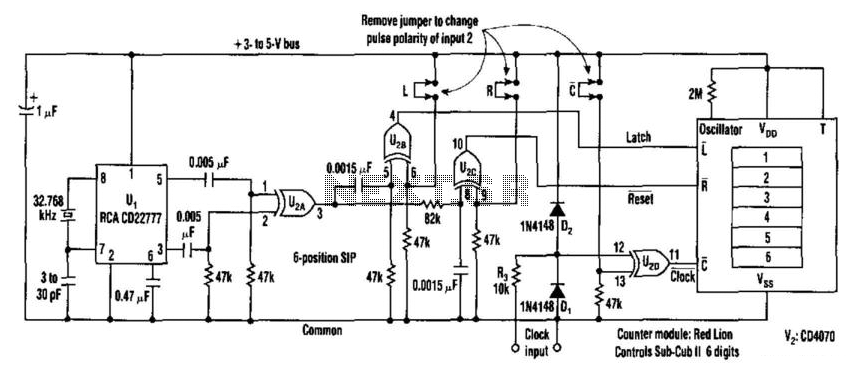
1Hz Timebase For Readout And Counter Applications
This counter facilitates the direct readout of frequency-generating equipment by incorporating a 1-Hz time base to latch, reset, and condition the count signal. The design allows for the selection of either polarity. By differentiating, inverting, and ORing the clock pulses...
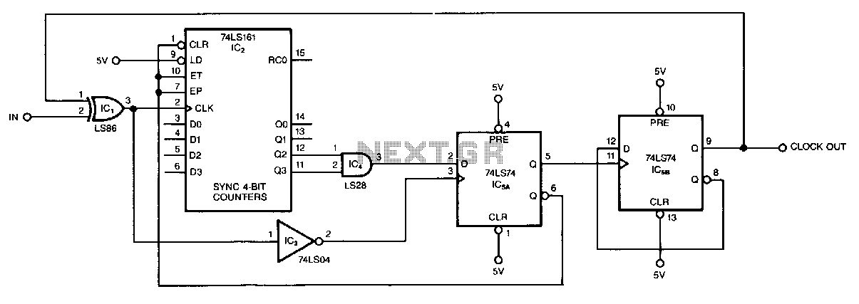
Odd-number-counter-divider
This circuit, illustrated symmetrically, divides an input by virtually any odd number. The circuit counts n + 1/2 clocks twice to achieve the desired divisor. By selecting the appropriate n, which is the decoded output of the LS161 counter, divisors...
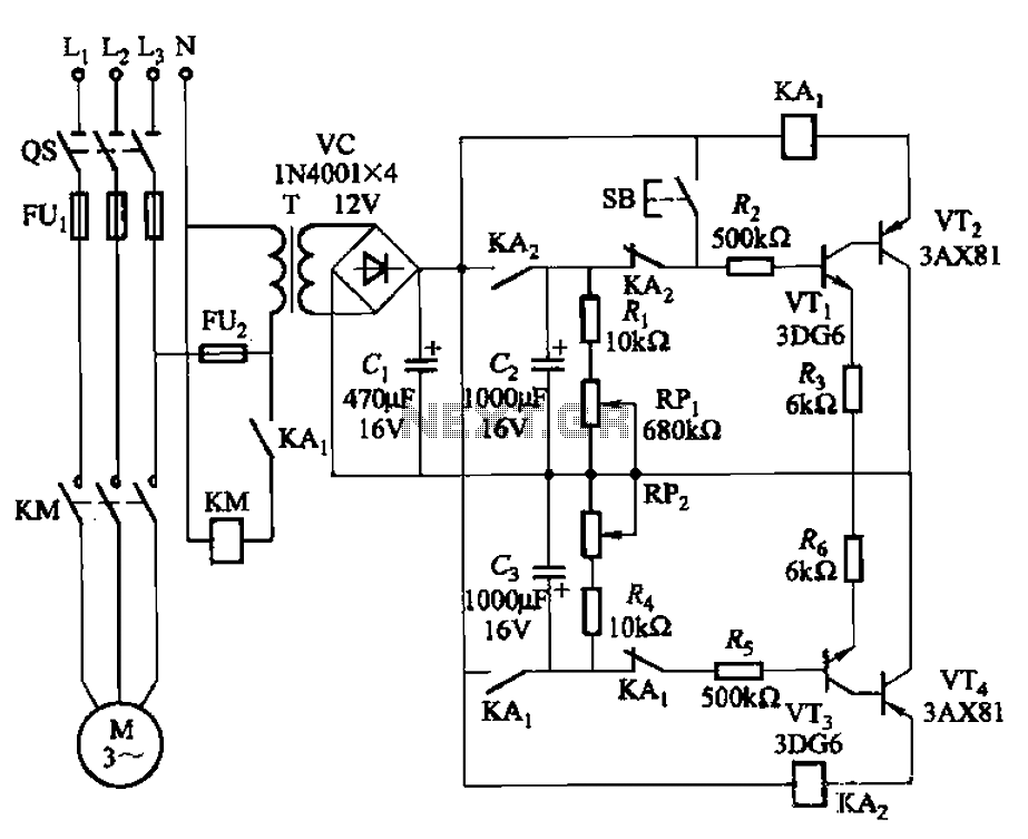
Intermittent start and stop cycle control circuit of the four
The circuit illustrated in Figure 3-79 consists of two delay circuits. The RPi adjustment potentiometer and RP2 can be modified to control the duration of the motor operation, allowing for arbitrary adjustments within a specified time frame.
The circuit comprises two...
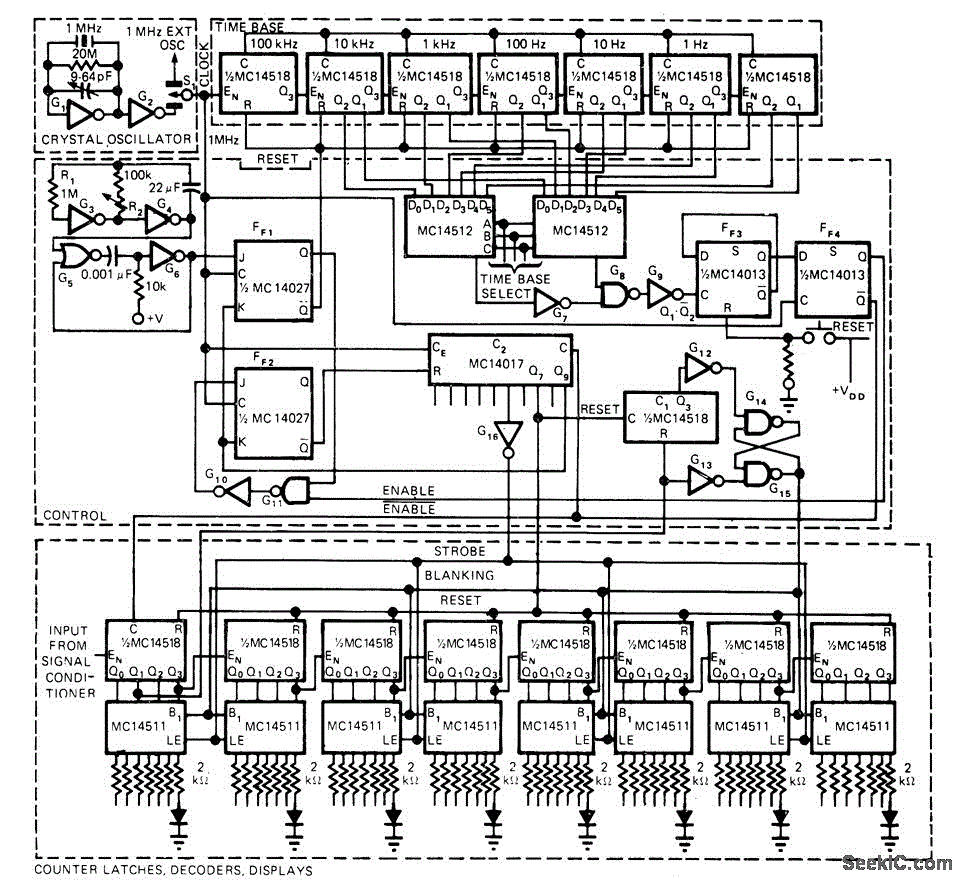
12V 5MHz COUNTER
The portable counter is designed with low-power logic to minimize battery drain while maintaining good performance. Since most of the milliwatt power drain is consumed by the digital readout, the circuit blanks the LED display when there is no input...
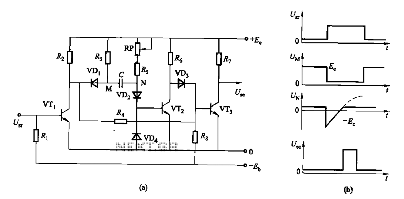
As control the discharge tube type delay circuit
The circuit described is a discharge delay circuit that offers a longer delay compared to a standard rechargeable delay circuit, while also maintaining relatively high accuracy. The schematic diagram illustrates the input and output waveforms. Typically, when there is no...
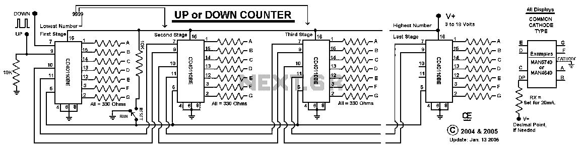
Digital Up / Down Counter
This Circuit uses a CD40110BE, Up/Down Counter IC's. This IC is able to Source Each Segment with 25 mA, Giving a Very Nice Bright Display. The 7 Segment Displays MUST be a Common Cathode Type, as I have used here....
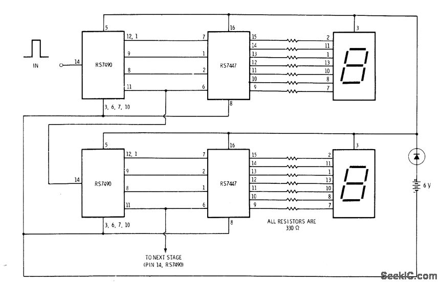
MULTIDIGIT DEMONSTRATION COUNTER
A simple interconnection of the RS7490 decade counter, RS7447 decoder, and a 7-segment digital display for each desired digit creates an ideal counter for classroom demonstrations and science fair exhibits. With the addition of two extra stages, the display can...
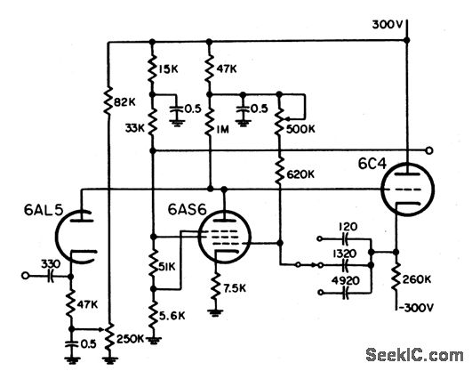
NONPRECISE PHANTASTRON VARIABLE DELAY
This circuit is designed to delay the start of the cathode ray tube (CRT) sweep for an expanded display. It offers three range settings: 0 to 5 miles, 60 miles, and 200 miles. The circuit primarily utilizes a cathode-coupled phantastron,...
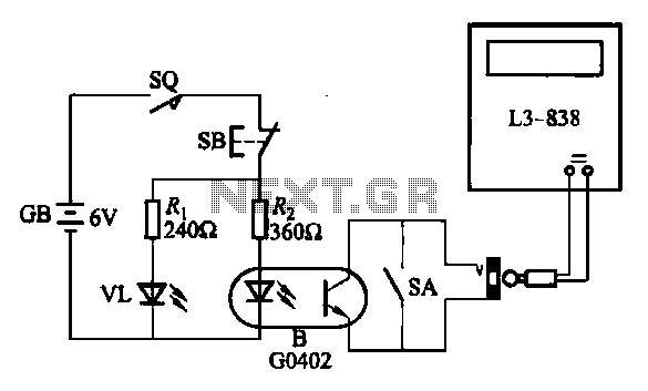
Electronic counter with automatic counting interface circuit a
An electronic calculator features an automatic counting interface circuit, as illustrated in the accompanying figures. Figure (a) depicts a stroke switch controlled via optocoupler B. Figure (b) shows the application of a reed switch (KR) for pulse control signals. Figure...