


Relay Timer with ATmega8 AVR MCU
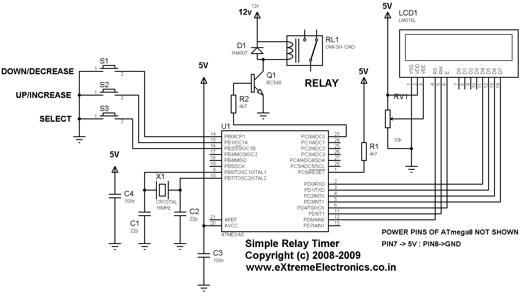
Description: A simple timer that can be used to turn a load on or off after a user-specified time. The prototype was developed using the xBoard MINI, a low-cost and easy-to-use ATmega8 development board. The program was burned to the MCU's flash memory using eXtreme Burner - AVR Software and Hardware. The Simple Device Timer project is designed using the ATmega8 AVR MCU. The timer is useful for keeping a device "ON" for a specific period. Once the set time elapses, the timer automatically turns the load off. The timer utilizes a standard 16x2 LCD module for the user interface. The user can set the time using a 3-button keypad. After setting the time, the timer is started, and while the countdown is in progress, the remaining time is displayed on the screen. The program utilizes an LCD driver library, with more details available on the website. The avr-gcc compiler and AVR Studio are used for compilation.
The Simple Device Timer circuit employs an ATmega8 microcontroller, which serves as the core processing unit. The ATmega8 is a versatile 8-bit AVR microcontroller featuring 8 KB of flash memory, 1 KB of SRAM, and 512 bytes of EEPROM, making it suitable for various applications, including timing and control tasks. The xBoard MINI development board provides a convenient platform for prototyping, integrating essential components like power supply, crystal oscillator, and programming interface.
The timer's user interface is facilitated by a 16x2 LCD module, which displays the countdown timer and allows users to interact through a 3-button keypad. The keypad typically consists of three buttons: one for increasing the time, one for decreasing it, and one for starting the timer. The microcontroller reads the button presses through its digital input pins, enabling user input to adjust the timing parameters.
The countdown functionality is implemented through an interrupt-driven approach, where the microcontroller utilizes its internal timers to keep track of elapsed time. Once the user sets the desired time and starts the timer, the program enters a loop that continuously updates the LCD display with the remaining time. When the countdown reaches zero, the microcontroller activates a relay or transistor to turn off the connected load, ensuring that the device operates only for the specified duration.
The use of the avr-gcc compiler and AVR Studio for development allows for efficient programming and debugging of the microcontroller, ensuring reliable operation of the timer. The inclusion of an LCD driver library simplifies the process of controlling the LCD module, enabling smooth updates to the display without extensive coding overhead. Overall, this Simple Device Timer project exemplifies an effective application of microcontroller technology in creating user-friendly timing solutions.A simple timer that can be used to turn on/off a load after user specified time. The prototype was developed using xBoard MINI, a low cost easy to use ATmega8 development board. The program was burned to the MCU`s flash memory using eXtreme Burner - AVR Software and Hardware. The Simple Device Timer project designed using ATmega8 AVR MVU. The Timer is usefully for keeping a device "ON" for a specific period of time. After the set time elapse the timer automatically turns the load off. The Timer uses a standard 16x2 lcd module for user interface UI. User can set the time using a 3 button keypad. After that Timer is started. While count down is in progress, the time left is displayed on screen. The program use our LCD driver library more details of which can be found in Web site. Use avr-gcc + AVR Studio to compile.
The Simple Device Timer circuit employs an ATmega8 microcontroller, which serves as the core processing unit. The ATmega8 is a versatile 8-bit AVR microcontroller featuring 8 KB of flash memory, 1 KB of SRAM, and 512 bytes of EEPROM, making it suitable for various applications, including timing and control tasks. The xBoard MINI development board provides a convenient platform for prototyping, integrating essential components like power supply, crystal oscillator, and programming interface.
The timer's user interface is facilitated by a 16x2 LCD module, which displays the countdown timer and allows users to interact through a 3-button keypad. The keypad typically consists of three buttons: one for increasing the time, one for decreasing it, and one for starting the timer. The microcontroller reads the button presses through its digital input pins, enabling user input to adjust the timing parameters.
The countdown functionality is implemented through an interrupt-driven approach, where the microcontroller utilizes its internal timers to keep track of elapsed time. Once the user sets the desired time and starts the timer, the program enters a loop that continuously updates the LCD display with the remaining time. When the countdown reaches zero, the microcontroller activates a relay or transistor to turn off the connected load, ensuring that the device operates only for the specified duration.
The use of the avr-gcc compiler and AVR Studio for development allows for efficient programming and debugging of the microcontroller, ensuring reliable operation of the timer. The inclusion of an LCD driver library simplifies the process of controlling the LCD module, enabling smooth updates to the display without extensive coding overhead. Overall, this Simple Device Timer project exemplifies an effective application of microcontroller technology in creating user-friendly timing solutions.A simple timer that can be used to turn on/off a load after user specified time. The prototype was developed using xBoard MINI, a low cost easy to use ATmega8 development board. The program was burned to the MCU`s flash memory using eXtreme Burner - AVR Software and Hardware. The Simple Device Timer project designed using ATmega8 AVR MVU. The Timer is usefully for keeping a device "ON" for a specific period of time. After the set time elapse the timer automatically turns the load off. The Timer uses a standard 16x2 lcd module for user interface UI. User can set the time using a 3 button keypad. After that Timer is started. While count down is in progress, the time left is displayed on screen. The program use our LCD driver library more details of which can be found in Web site. Use avr-gcc + AVR Studio to compile.
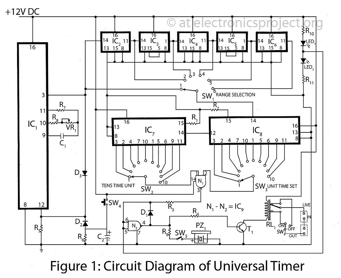
The Universal Timer with description
The Universal Timer is a highly versatile timer project that accommodates a wide range of time periods, from 1/10th of a second to 100 hours. This circuit diagram includes a comprehensive description of various timer circuits associated with the universal...
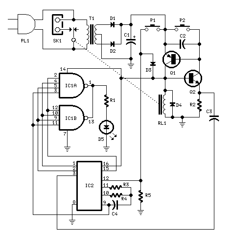
Bedside Lamp Timer
The purpose of this circuit is to power a lamp or other apparatus for a specified duration (30 minutes in this case) and then turn it off. It is particularly useful for reading in bed at night, as it automatically...
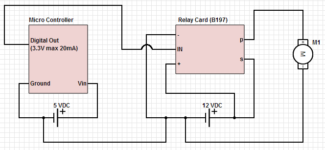
Common ground for different voltages in relay circuit
The objective is to control a 12 VDC device (on/off) from a microcontroller using a relay card. The relay requires a 12 VDC operating power supply.
To achieve the control of a 12 VDC device using a microcontroller and a relay...
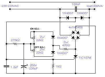
Mains variable Delay circuit
The circuit shown will switch on and off a resistive or inductive load up to 800VA with the possibility to adjust both the on and off period. Switching takes place during the zero crossing of the sine wave. The switch...
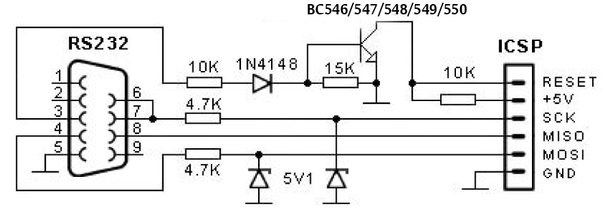
AVR Serial Port Programmer
The entire AVR programmer has been built using common parts and fits in the case of the serial connector. The socket PCB has been created to accommodate a 28-DIP AVR ATmega8 microcontroller, but a socket PCB can be designed for...
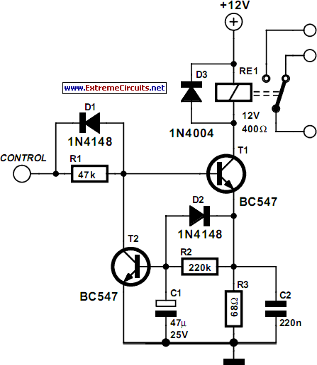
Energy Saver Relay Coil circuit and explanation
Some relays will become warm if they remain energized for some time. The circuit shown here will actuate the relay as before but then reduce the hold current through the relay coil by about 50%, thus considerably reducing the amount...
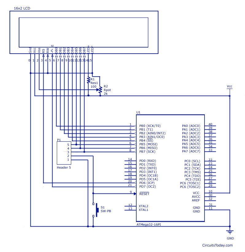
LCD Interfacing with AVR-Atmega8 and Atmega32
Interfacing an LCD display with AVR microcontrollers, specifically the Atmega8 and Atmega32, including a circuit diagram and embedded C code for implementation.
The interfacing of an LCD display with AVR microcontrollers, such as the Atmega8 and Atmega32, is a common task...
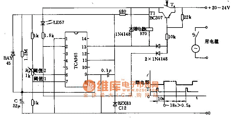
Timer circuit with 106 fixed preset time
The foot 13 between valve value 1 and valve value 2 will draw the transistor base current. If the relay releases, after a recovery time of 0.5 seconds, pressing the key will initiate the switching process again. The timer is...
thermometer dengan avr
The module provides a pre-wired multiplex of a 4-digit common anode LED, which is quite useful. The soldering pad for these signals is shown in the first picture below. A friend provided an AT90S2313 chip, along with a simple homemade...