


Set Timing Calculator With The LM555IC
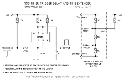
Description: The following circuit illustrates a Set Timing Calculator Circuit. This circuit is based on the LM555 integrated circuit. Features include the provision of a delay of approximately...
The Set Timing Calculator Circuit utilizing the LM555 integrated circuit (IC) is designed to generate precise time delays based on external component values. The LM555 is a versatile timer IC that can be configured in various modes, including monostable and astable operation. In the monostable configuration, the circuit generates a single output pulse of a specific duration upon receiving a trigger signal.
In this circuit, the timing interval is determined by the resistor (R) and capacitor (C) values connected to the LM555. The time delay (T) can be calculated using the formula:
T = 1.1 × R × C
Where:
- T is the time delay in seconds,
- R is the resistance in ohms,
- C is the capacitance in farads.
The components selected for R and C will dictate the length of the delay. For example, if a resistor of 100 kΩ and a capacitor of 10 µF are used, the calculated delay would be approximately 1.1 seconds.
The circuit typically includes a trigger input that activates the timing sequence. When a low voltage signal is applied to this input, the output of the LM555 goes high, and the timing cycle begins. After the designated time interval, the output returns to its low state. This behavior makes the circuit suitable for applications such as timers, pulse generators, and delay circuits in various electronic projects.
Additional components may include diodes for protection against reverse polarity and capacitors for noise filtering to ensure stable operation. The circuit can be powered using a standard DC voltage supply, typically ranging from 5V to 15V, depending on the specific requirements of the application. Proper layout and connection of components are crucial for optimal performance and reliability of the timing calculator circuit.The following circuit shows about Set Timing Calculator Circuit. This Circuit based on the LM555IC. Features: provide a delay of approximately ..
The Set Timing Calculator Circuit utilizing the LM555 integrated circuit (IC) is designed to generate precise time delays based on external component values. The LM555 is a versatile timer IC that can be configured in various modes, including monostable and astable operation. In the monostable configuration, the circuit generates a single output pulse of a specific duration upon receiving a trigger signal.
In this circuit, the timing interval is determined by the resistor (R) and capacitor (C) values connected to the LM555. The time delay (T) can be calculated using the formula:
T = 1.1 × R × C
Where:
- T is the time delay in seconds,
- R is the resistance in ohms,
- C is the capacitance in farads.
The components selected for R and C will dictate the length of the delay. For example, if a resistor of 100 kΩ and a capacitor of 10 µF are used, the calculated delay would be approximately 1.1 seconds.
The circuit typically includes a trigger input that activates the timing sequence. When a low voltage signal is applied to this input, the output of the LM555 goes high, and the timing cycle begins. After the designated time interval, the output returns to its low state. This behavior makes the circuit suitable for applications such as timers, pulse generators, and delay circuits in various electronic projects.
Additional components may include diodes for protection against reverse polarity and capacitors for noise filtering to ensure stable operation. The circuit can be powered using a standard DC voltage supply, typically ranging from 5V to 15V, depending on the specific requirements of the application. Proper layout and connection of components are crucial for optimal performance and reliability of the timing calculator circuit.The following circuit shows about Set Timing Calculator Circuit. This Circuit based on the LM555IC. Features: provide a delay of approximately ..
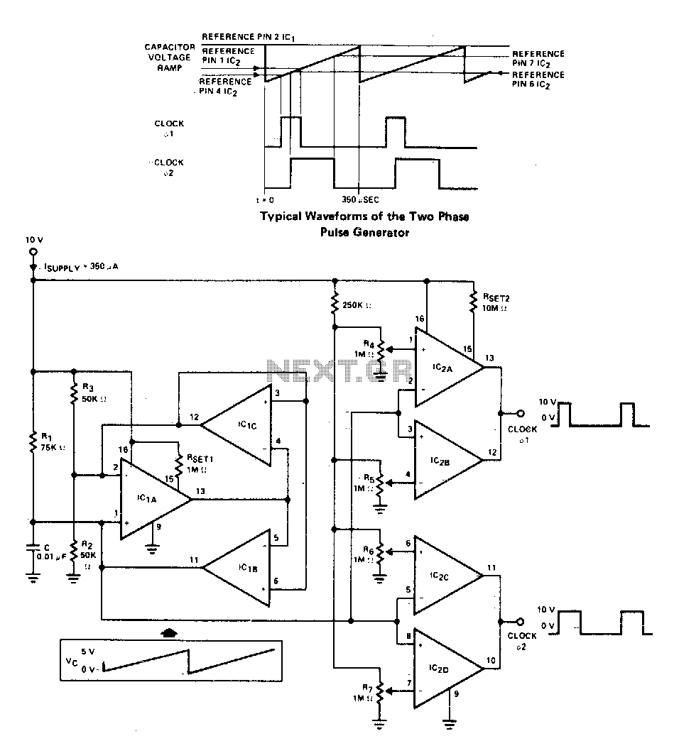
Versatile two-phase pulse generator
A two-phase clock generator utilizes two L161 integrated circuits to produce pulses with adjustable widths and phase relationships. Additionally, a ramp generator supplies input to two variable window comparators, which are configured using IC2A-IC2B and IC2C-IC2D, respectively.
The two-phase clock generator...
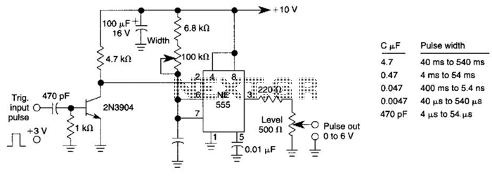
Add-On Pulse Generator Circuit
This pulse generator can enhance a standalone pulse generator. By utilizing a transistor and a 555 timer, it can produce pulse widths ranging from 5 microseconds to 500 microseconds. The value of capacitor C3 can be approximately determined using the...
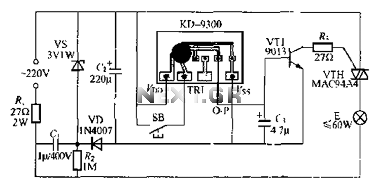
Using music integrated circuit delay lamp
The circuit utilizes a KD-9300 music IC, which activates when the button switch (SB) is pressed, causing the electric lamp (E) to light up for approximately 20 seconds before automatically turning off. The setup includes a half-wave rectifier and a...

Pulse Generator Circuit
By utilizing a 556 dual timer, with IC1A functioning as a waveshaper and IC1B as a pulse generator, a pulse width range of 10:1 can be achieved. This circuit can be triggered using a sine wave.
The circuit operates on the...
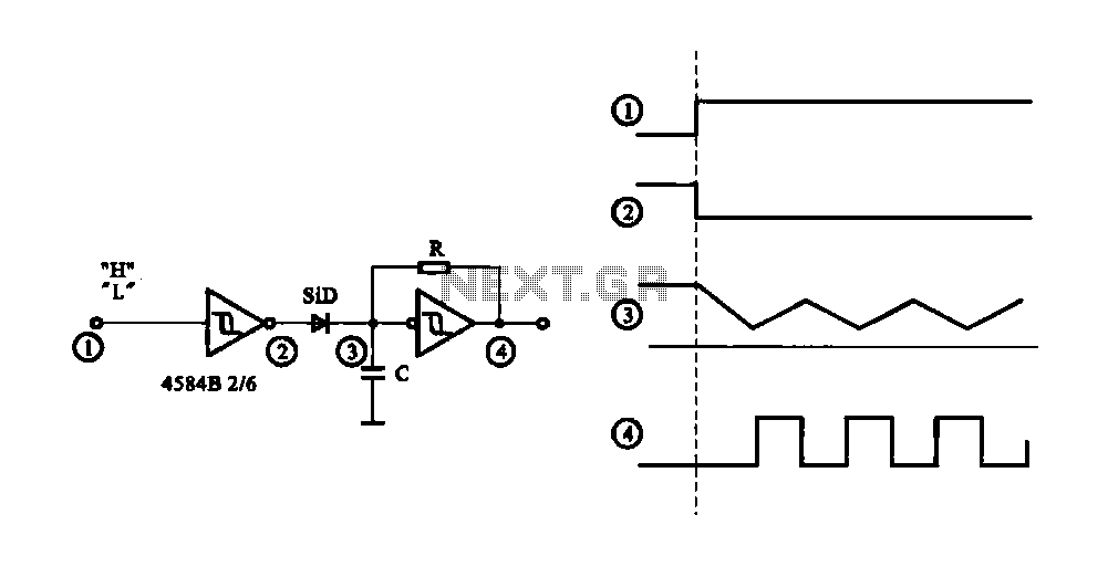
Controlled pulse signal generating circuit
The circuit generates a controlled pulse signal. When a high pulse signal is applied to the input terminal O (start), the output pulse signal is activated. Conversely, when a low signal is received at the input terminal O (stop), the...
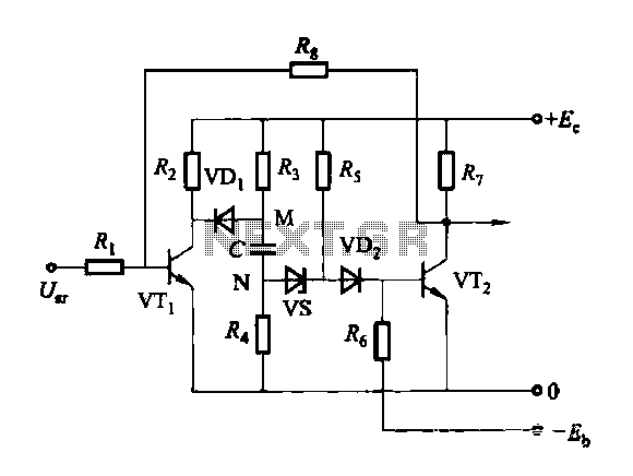
Discharge before memory circuit
Discharge before memory circuit. Before the memory circuit is activated, a delay reset circuit is required. When the input signal triggers an action, timing begins, and after a specified delay, the circuit reverts to its original state. During this interval,...

In-Car lights delay circuit
This circuit switch slowly on and off the internal lights in a car. The delaying time can be adjusted changing the values of the 10k, 4M7 resistors and capacitor. More: The BUZ74 can handle voltages of 500V, but you can...
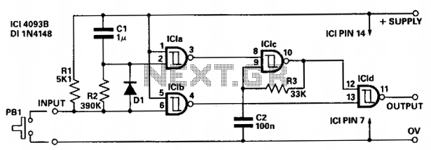
Delayed pulse generator
The circuit provides independent control of the initial delay and pulse rate. ICIc functions as a pulse generator, with its operation inhibited by the normally low output of ICla. When the circuit input transitions to low (e.g., when pressing PB1),...
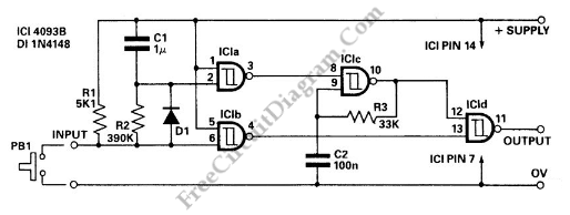
Pulse Delay Generator
This circuit is a delayed pulse generator that provides pulse rate and independent control of the initial delay. The pulse generator of this circuit is.
The delayed pulse generator circuit is designed to produce a pulse output after a specified delay,...