


Simple timer circuit MC14541
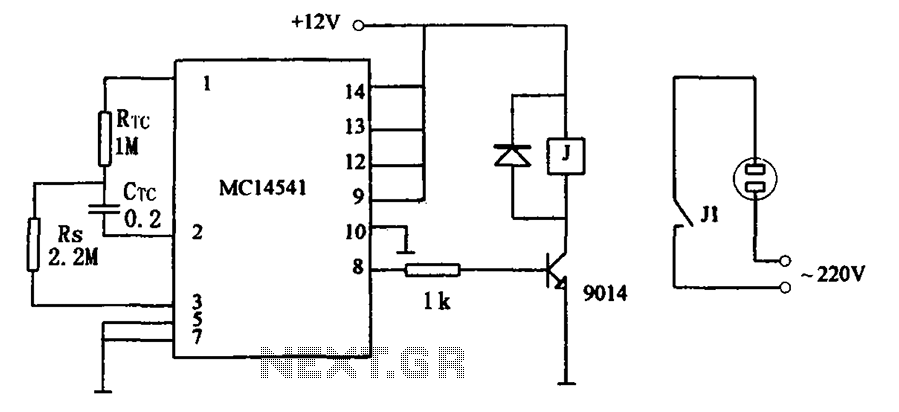
Description: The circuit illustrated in FIG MC14541 is a straightforward timing circuit utilizing the MC14541 integrated circuit (IC). By adjusting the parameter map, the timing can be set for a duration of 3 hours, with options to select various RTC, CTC, and Rs values to achieve the required timing control.
The MC14541 timing circuit is designed to provide precise timing functions for various applications. It operates by employing a combination of resistors (Rs), capacitors, and the integrated circuit itself to generate a stable time delay. The choice of RTC (Real-Time Clock) and CTC (Clock Time Constant) values plays a critical role in defining the timing characteristics of the circuit.
In this circuit, the MC14541 IC serves as the core timing element, which is capable of producing accurate delays through its internal architecture. The timing duration can be set to 3 hours, making it suitable for applications that require long-term timing operations. Adjustments to the parameter map allow for flexibility in timing configurations, which can be tailored to specific requirements.
The selection of resistor and capacitor values influences the timing intervals significantly. For instance, a higher resistance value in conjunction with a larger capacitor will extend the timing duration, while lower values will shorten it. This adaptability enables the circuit to be utilized in various scenarios, from simple timing tasks to more complex applications where precise timing is essential.
Overall, the MC14541 timing circuit is an efficient solution for implementing timing functions, providing versatility through its adjustable parameters and the ability to customize timing durations according to user needs. As shown in FIG MC14541 constituted by a simple timing circuit. The circuit uses IC MC14541 constitute a simple timing circuit. Press the parameter map, the timing for 3 hours, and can choose different RTC, CTC and Rs values. In order to achieve the desired timing control.
The MC14541 timing circuit is designed to provide precise timing functions for various applications. It operates by employing a combination of resistors (Rs), capacitors, and the integrated circuit itself to generate a stable time delay. The choice of RTC (Real-Time Clock) and CTC (Clock Time Constant) values plays a critical role in defining the timing characteristics of the circuit.
In this circuit, the MC14541 IC serves as the core timing element, which is capable of producing accurate delays through its internal architecture. The timing duration can be set to 3 hours, making it suitable for applications that require long-term timing operations. Adjustments to the parameter map allow for flexibility in timing configurations, which can be tailored to specific requirements.
The selection of resistor and capacitor values influences the timing intervals significantly. For instance, a higher resistance value in conjunction with a larger capacitor will extend the timing duration, while lower values will shorten it. This adaptability enables the circuit to be utilized in various scenarios, from simple timing tasks to more complex applications where precise timing is essential.
Overall, the MC14541 timing circuit is an efficient solution for implementing timing functions, providing versatility through its adjustable parameters and the ability to customize timing durations according to user needs. As shown in FIG MC14541 constituted by a simple timing circuit. The circuit uses IC MC14541 constitute a simple timing circuit. Press the parameter map, the timing for 3 hours, and can choose different RTC, CTC and Rs values. In order to achieve the desired timing control.
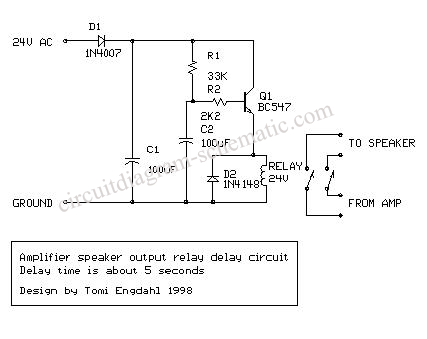
Circuit Delay and Speakers Protektor Using TL071
The circuit-delay relay for speakers serves as a delay mechanism that prevents the immediate activation of speakers when the amplifier is powered on. This feature is designed to protect the speakers from potential damage caused by sudden power surges. The...
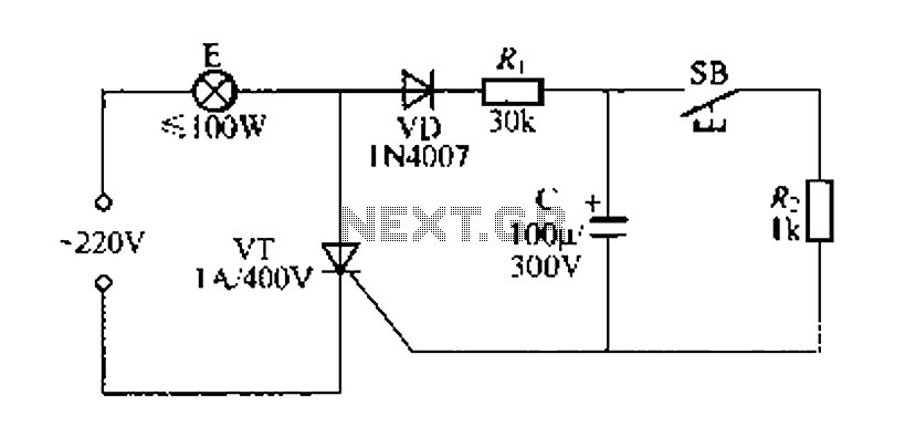
Simple delay lamp circuit 1
Figure 57 illustrates a simple delay lamp circuit that connects to lamp E using a two-wire connection. This design allows for the security bars to be installed directly, enabling replacement with a standard wall switch without altering the existing interior...
EGR 450 Manufacturing Controls Project
A timing and counting circuit utilizing integrated circuit chips with seven-segment LED displays is employed to show the current lap time, previous lap time, and total number of laps completed on a 1/64th-scale slot car racetrack. A switch activated by...
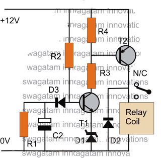
make this simple delay on timer circuit
The post discusses a simple delay ON circuit that enables a connected load at the output to be activated with a predetermined delay after the power switch is turned ON. This circuit can be utilized in various applications that require...
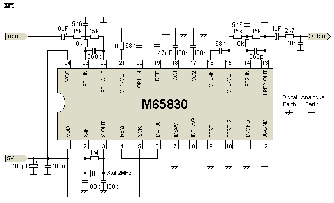
The Delay
The delay circuit utilizes the Mitsubishi M65830 Digital Delay chip, as illustrated in Figure 1. This chip has been in use for some time and is known for its simplicity and effectiveness, particularly when a fixed delay is sufficient. However,...
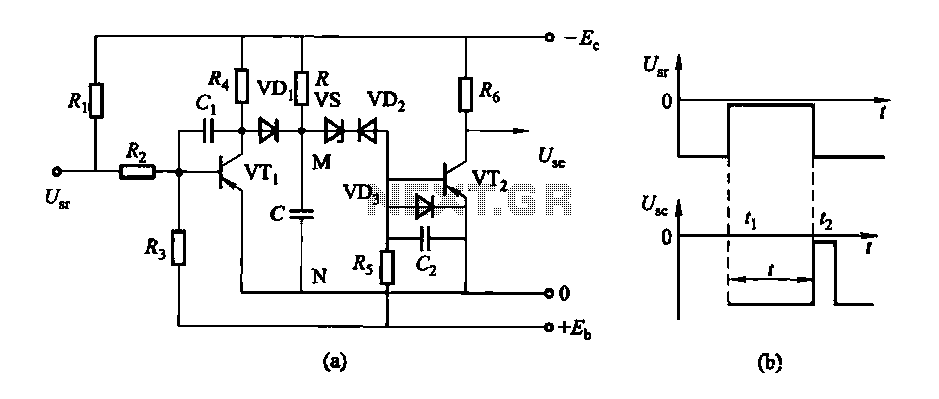
Conducting pipe control rechargeable delay circuit
The circuit features a delay action with an instantaneous reset control mechanism. It is categorized into three types: a conducting pipe rechargeable delay circuit, a tube cut-off control rechargeable delay circuit, and a discharge-type delay circuit. In the conducting pipe...
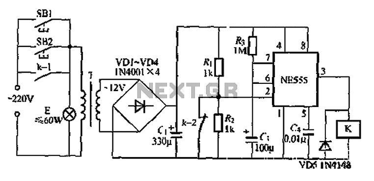
When using the lamp base circuit delay circuit 2
Another application involves the use of a NE555 delay lamp circuit, where components SB1 and SH2 act as J-light buttons that can be installed in two different locations. The lamp can be activated by pressing either SB1 or SB2, which...
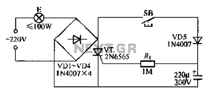
Simple light delay circuit 3
This circuit is a simple connection delay lamp circuit. When the lights are turned on and the switch is pressed, the power supply is activated. The capacitor charges rapidly, causing the thyristor (VT) to open, which in turn lights up...
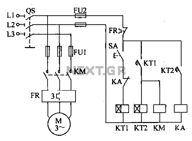
Automatic delay the start of operation of the circuit
After the power switch is activated, the motor does not start immediately but instead has a specified delay period. This setup allows the machine to perform automatic intermittent lubrication control. The circuit for the motor boot delay and intermittent operation...