


The series connecting control circuit of electric contact pressure gauge and time relay
#time relay
#electric contact pressure gauge
#motor control
#pressure sensor
#automation
#delay circuit
#control circuit
#industrial
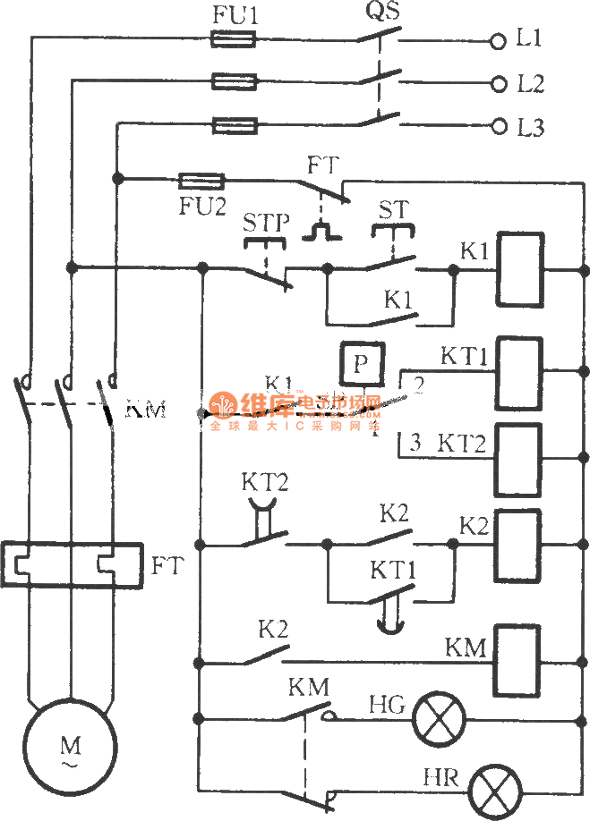
Description: The circuit utilizes two time relays, KT1 and KT2, which are connected in series with the contacts of an electric contact pressure gauge (SP). This configuration helps to mitigate issues such as tremors or sparking that may occur due to the incomplete separation and contact of the SP during the motor's automatic start or stop phase, particularly when liquid or gas pressure has not yet been reached.
The circuit design features two time relays, KT1 and KT2, which play a crucial role in managing the operational timing of the electric contact pressure gauge (SP). The relays are strategically connected in series with the gauge to ensure that the system operates smoothly without the risk of electrical arcing or mechanical wear caused by premature contact.
When the system is activated, the time relays introduce a delay before the gauge contacts close, allowing sufficient time for the pressure to stabilize. This delay is essential to prevent the gauge from reacting to transient pressures that could occur during the motor's start-up or shutdown phases. The relays are selected based on their time delay characteristics to match the specific requirements of the application, ensuring that the pressure readings are accurate and reliable.
The relay contacts are designed to handle the electrical load of the motor control circuit, providing a safe interface between the pressure gauge and the motor's control system. The series connection ensures that both relays must be activated for the circuit to complete, adding an additional layer of safety and redundancy.
Furthermore, the circuit may include protective features such as fuses or circuit breakers to safeguard against overload conditions. Proper grounding and shielding techniques should also be implemented to minimize electromagnetic interference and enhance the overall reliability of the system.
Overall, the integration of time relays with an electric contact pressure gauge in this circuit design significantly improves the operational stability and safety of the motor control system, particularly in applications where pressure fluctuations are common.As shown in Figure, the circuit usestwo time relays KT1, KT2 to connect with thecontactsofelectric contact pressure gauge SP in series. When liquid or gas pressure has not yet reached, it can overcome thetrembling or spark phenomenons because of the SP`s incomplete separating andtoucing in the crash time of motor automatic start or stop,and itimprovesthe re..
The circuit design features two time relays, KT1 and KT2, which play a crucial role in managing the operational timing of the electric contact pressure gauge (SP). The relays are strategically connected in series with the gauge to ensure that the system operates smoothly without the risk of electrical arcing or mechanical wear caused by premature contact.
When the system is activated, the time relays introduce a delay before the gauge contacts close, allowing sufficient time for the pressure to stabilize. This delay is essential to prevent the gauge from reacting to transient pressures that could occur during the motor's start-up or shutdown phases. The relays are selected based on their time delay characteristics to match the specific requirements of the application, ensuring that the pressure readings are accurate and reliable.
The relay contacts are designed to handle the electrical load of the motor control circuit, providing a safe interface between the pressure gauge and the motor's control system. The series connection ensures that both relays must be activated for the circuit to complete, adding an additional layer of safety and redundancy.
Furthermore, the circuit may include protective features such as fuses or circuit breakers to safeguard against overload conditions. Proper grounding and shielding techniques should also be implemented to minimize electromagnetic interference and enhance the overall reliability of the system.
Overall, the integration of time relays with an electric contact pressure gauge in this circuit design significantly improves the operational stability and safety of the motor control system, particularly in applications where pressure fluctuations are common.As shown in Figure, the circuit usestwo time relays KT1, KT2 to connect with thecontactsofelectric contact pressure gauge SP in series. When liquid or gas pressure has not yet reached, it can overcome thetrembling or spark phenomenons because of the SP`s incomplete separating andtoucing in the crash time of motor automatic start or stop,and itimprovesthe re..
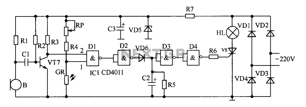
Delay circuit diagram of energy-saving lamps
The delay-saving lamp circuit functions as a sound and light control delay energy-saving lighting system. It can directly replace a standard light switch without modifying the existing lighting circuits. In bright or daytime conditions, the sound control feature ensures that...
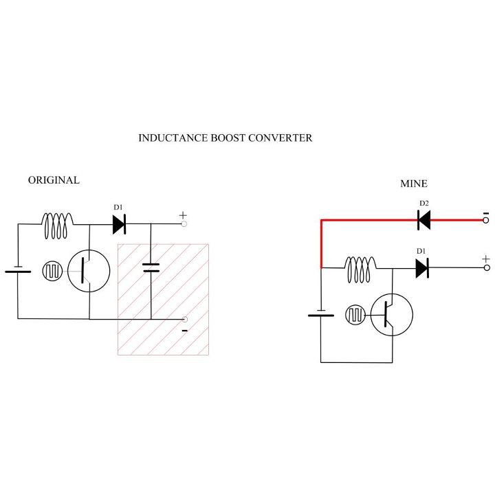
My Motors got me to Tap into Radiant Energy
A new user is seeking to share information about their experiences on this platform.
The user expresses a desire to communicate and engage with the community regarding their experiences. This indicates an interest in exchanging knowledge and possibly seeking assistance or...
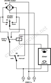
To Automate Rolling Shutter Motor
To automate the opening and closing of a rolling shutter using a time-controlled switch, additional wiring will be necessary.
To implement an automated system for a rolling shutter, a time-controlled switch can be utilized to manage the operation of the shutter....
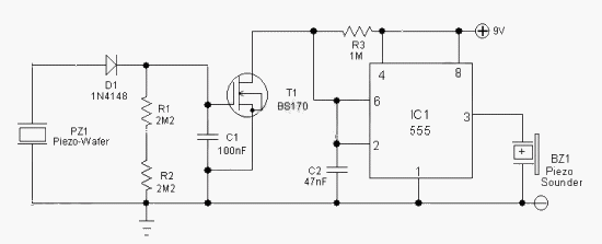
Pressure Sensor Alarm
The general-purpose circuit of the simple pressure sensor alarm is constructed using a few easily accessible and inexpensive components. The operation of this circuit is straightforward.
The simple pressure sensor alarm circuit typically includes a pressure sensor, an operational amplifier (op-amp),...
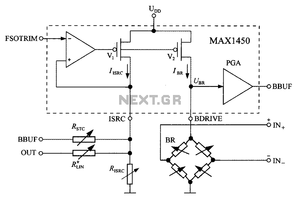
Bridge integrated pressure signal conditioner MAX1450 drive circuit diagram
The circuit diagram for the bridge integrated pressure signal conditioner MAX1450 is composed of various components.
The MAX1450 is a high-performance integrated circuit designed for signal conditioning in pressure sensing applications. It is particularly suited for use with resistive bridge sensors,...

Pressure
The MPX4100 is a pressure sensor that includes a signal conditioning circuit and a temperature calibrator, ensuring stability against temperature variations. It utilizes micro-machining techniques, thin film metallization, and bipolar semiconductor processes to achieve measurement accuracy. The signal conditioning circuit...
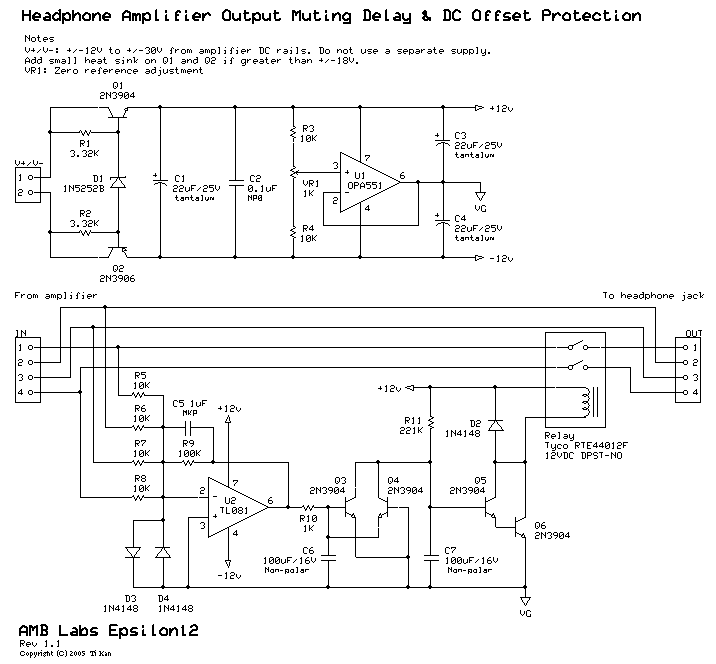
A muting delay & DC offset protection circuit
A low-pass filter is a stable state-space system that has an input and produces an output. If the input is a quasi-periodic signal, the output will be the same quasi-periodic signal with a phase shift. The key difference is that...

Conducting pipe rechargeable long delay control circuit
Conducting pipe rechargeable long delay control circuit. An adjustment potentiometer RP can delay up to several tens of seconds.
The conducting pipe rechargeable long delay control circuit is designed to manage the timing of electrical signals, allowing for a delay that...
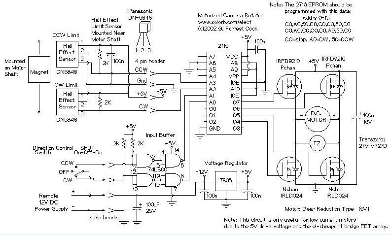
Motorized Video Camera Mount
The camera rotator circuit utilizes a 2716 EPROM to store a logic value table that governs the motor driver (H-bridge) circuit. The schematic illustrates the EPROM data. By employing the EPROM, a significant number of discrete gates are eliminated. The...