


Time-delayed relay
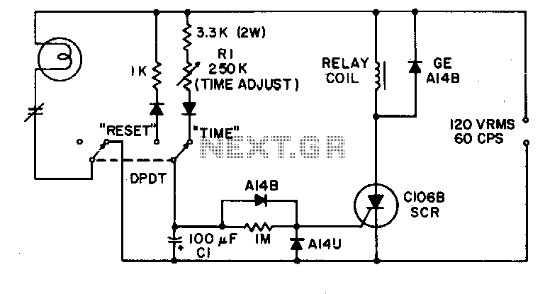
Description: This simple timing circuit can delay an output switching function from 1 second to about 1 minute. The SCR is triggered by only a few microamps from the timing network R1-C1 to energize the output relay.
The timing circuit described employs a silicon-controlled rectifier (SCR) as the primary switching element, utilizing a resistor-capacitor (R-C) timing network to establish the desired delay. The timing network consists of resistor R1 and capacitor C1, which work together to create a time constant that governs the delay before the output relay is activated.
Upon powering the circuit, capacitor C1 begins to charge through resistor R1. The time it takes for the capacitor to charge to a specific voltage level, typically the gate trigger voltage of the SCR, determines the duration of the delay. The relationship between the resistance (R1), capacitance (C1), and the voltage across the capacitor can be described by the formula:
\[ t = R1 \times C1 \times \ln\left(\frac{V_{supply}}{V_{supply} - V_{trigger}}\right) \]
where \( t \) is the time delay, \( V_{supply} \) is the supply voltage, and \( V_{trigger} \) is the gate trigger voltage of the SCR.
Once the voltage across C1 reaches the gate trigger threshold of the SCR, the SCR conducts, allowing current to flow through the output relay coil. This energizes the relay, closing its contacts and activating the connected load. The SCR remains in the conducting state until the current through it falls below a certain holding current threshold, at which point it turns off. This characteristic allows for the relay to remain activated for as long as the input power is maintained.
The circuit's design ensures that only a minimal amount of current, measured in microamps, is required to trigger the SCR, which makes it efficient and suitable for applications where low power consumption is critical. Overall, this timing circuit is ideal for applications requiring precise control of output timing, such as in automation systems, delay timers, or sequential control processes.This simple timing circuit can delay an output switching function from 1 seconds to about 1 minute The SCR is triggered by only a few microamps from the timing network Rl-Cl to energize the output relay.
The timing circuit described employs a silicon-controlled rectifier (SCR) as the primary switching element, utilizing a resistor-capacitor (R-C) timing network to establish the desired delay. The timing network consists of resistor R1 and capacitor C1, which work together to create a time constant that governs the delay before the output relay is activated.
Upon powering the circuit, capacitor C1 begins to charge through resistor R1. The time it takes for the capacitor to charge to a specific voltage level, typically the gate trigger voltage of the SCR, determines the duration of the delay. The relationship between the resistance (R1), capacitance (C1), and the voltage across the capacitor can be described by the formula:
\[ t = R1 \times C1 \times \ln\left(\frac{V_{supply}}{V_{supply} - V_{trigger}}\right) \]
where \( t \) is the time delay, \( V_{supply} \) is the supply voltage, and \( V_{trigger} \) is the gate trigger voltage of the SCR.
Once the voltage across C1 reaches the gate trigger threshold of the SCR, the SCR conducts, allowing current to flow through the output relay coil. This energizes the relay, closing its contacts and activating the connected load. The SCR remains in the conducting state until the current through it falls below a certain holding current threshold, at which point it turns off. This characteristic allows for the relay to remain activated for as long as the input power is maintained.
The circuit's design ensures that only a minimal amount of current, measured in microamps, is required to trigger the SCR, which makes it efficient and suitable for applications where low power consumption is critical. Overall, this timing circuit is ideal for applications requiring precise control of output timing, such as in automation systems, delay timers, or sequential control processes.This simple timing circuit can delay an output switching function from 1 seconds to about 1 minute The SCR is triggered by only a few microamps from the timing network Rl-Cl to energize the output relay.
Relay control circuit
The motor winding is configured with delta transposition capacitance, designated as cl-C-3G. It operates as a DC LAN speed generator and is associated with a three-phase asynchronous motor, which is coaxially connected through a field winding powered by a 10V...
build relay toggle switch
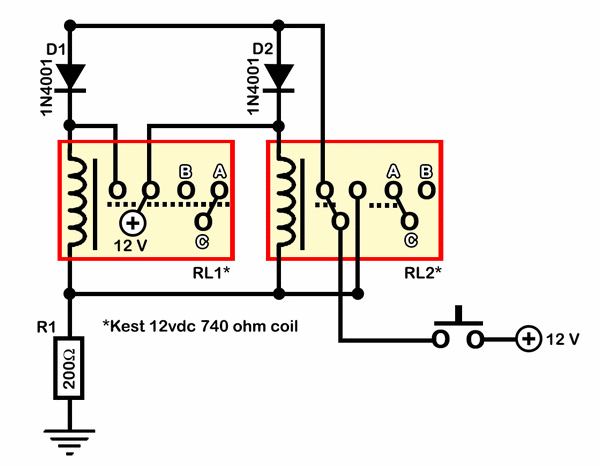
Half of RL1 and RL2 manage the switching mechanism, while the other half connects to an application. The relays operate at 200 ohms above ground, with one terminal referenced to positive voltage, which deactivates them. RL1, when off, applies a...
Single Transistor Relay Toggle Circuit
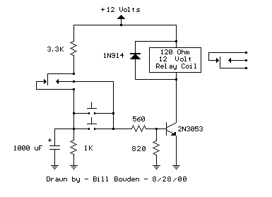
The circuit requires a double pole, double throw relay in conjunction with a single transistor to allow toggling the relay with a momentary push button. One set of relay contacts is used to control the load, while the other is...
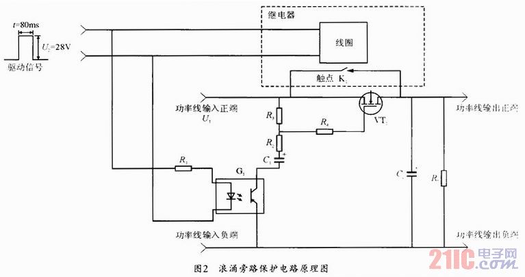
bypass which improves the ability to resist surging of relay contact
During the power-up of the apparatus, the capacitor is primarily responsible for the emergence of surge current. The schematic diagram of the principle is illustrated in Fig. 1. After K1 closes, the capacitor begins to charge, assuming that the direct...
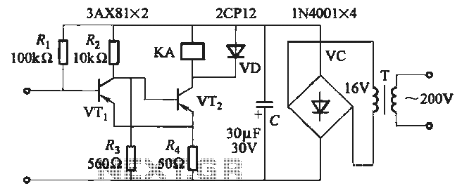
JB-22 transistor relay circuit
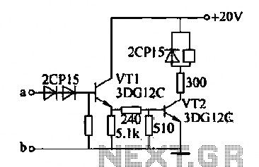
When the input is disconnected, the transistor VTi conducts, while VTz is in cutoff, causing relay KA to release. When the input is shorted, VTi is cut off, VTz conducts, and relay KA is activated.
In this circuit configuration, the operation...
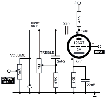
Schematic effect
The Echorec delay is an impressive piece of engineering. In their pursuit of perfection, Binson successfully addressed many critical design aspects, achieving a balance between simplicity and the integration of genuinely useful features in this classic echo machine. The engineers...
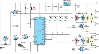
Relay Selector Pushbutton circuit and explanation
This circuit is designed for use in a hi-fi showroom, allowing for the selection of different speakers to connect to a stereo amplifier for comparative listening. It can also serve similar applications where only one device from a set needs...
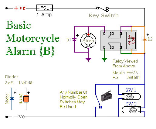
Two Relay-Based Motorcycle Alarm Circuits
These are two easy-to-build relay-based alarms. They can be used to protect a motorcycle, but they have many additional applications. When using relays with 6-volt coils, they can safeguard a classic bike. Both alarms are compact, with completed boards occupying...
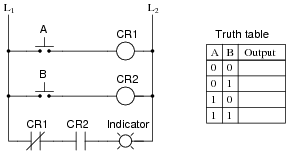
Electromechanical relay logic
In ladder logic symbolism, an electromechanical relay coil is depicted as a circle, while the contact(s) actuated by the coil are represented by two parallel lines, resembling a capacitor symbol. To interpret a ladder logic diagram, it is essential to...