


Universal wiper delay
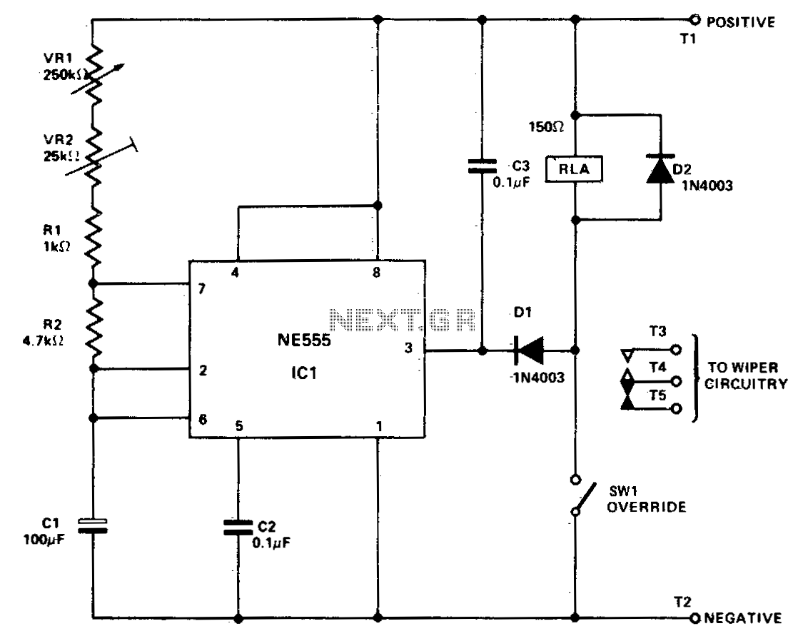
Description: IC1 is configured in astable mode, controlling relay RLA. Capacitors C3, diodes D1 and D2 are utilized to prevent voltage spikes from the relay coil and the wiper motor from activating IC1. Variable resistor VR2 is set to provide the minimum delay time required. Variable resistor VR1 serves as the primary delay control, offering a delay range from approximately 1 second to 20 seconds. Switch SW1 acts as an override mechanism to keep relay RLA permanently activated for standard wiper operation. Additionally, the relay must possess a minimum resistance of 150 ohms and feature heavy-duty contacts. A suppression circuit may be necessary to protect IC1.
The circuit utilizes an integrated circuit (IC) configured in astable mode, which generates a continuous square wave output. This output is responsible for controlling the operation of relay RLA, which in turn activates the wiper motor. The inclusion of capacitor C3 and diodes D1 and D2 serves a critical function in the circuit by suppressing voltage spikes that may occur when the relay coil is de-energized. These spikes can potentially damage IC1 or cause unintended operation, making the suppression components essential for circuit reliability.
Variable resistor VR2 is strategically implemented to allow fine-tuning of the minimum delay time, ensuring that the circuit can accommodate various operational requirements. In contrast, variable resistor VR1 is designed to provide a broader range of delay settings, enabling the user to adjust the delay from approximately 1 second to 20 seconds. This flexibility is particularly useful for applications where different delay intervals may be needed based on specific operational conditions or user preferences.
Switch SW1 serves a dual purpose; it functions as an override switch that enables the user to maintain relay RLA in a permanently activated state. This feature is particularly beneficial for scenarios requiring continuous wiper operation, allowing for manual control over the relay without the need for the timing circuit to engage.
The relay selected for this application must meet certain specifications, specifically a minimum resistance of 150 ohms, which ensures that it can effectively handle the current without overheating or failing. Additionally, the relay should be equipped with heavy-duty contacts to withstand the electrical load and mechanical wear associated with frequent operation.
To further enhance the protection of IC1, the inclusion of a suppression circuit is advisable. This circuit can be designed to mitigate any transient voltage spikes that may arise during the operation of the relay or the wiper motor, thereby safeguarding the integrity of the integrated circuit and ensuring long-term reliability of the overall system.ICl is connected in the astable mode, driving RLA, C3, Dl, and D2 prevent spikes from the relay coil and the wiper motor from triggering ICl. VR2 is adjusted to give the minimum delay time required. VR1 is the main delay control and pro vides a range of from about 1 second to 20 seconds. SW1 is an override switch to hold RLA permanently on (for normal wiper operation) The relay should have a resistance of at least 150 ohms and have heavy duty contacts. The suppression circuit may be needed for the protection of ICl.
The circuit utilizes an integrated circuit (IC) configured in astable mode, which generates a continuous square wave output. This output is responsible for controlling the operation of relay RLA, which in turn activates the wiper motor. The inclusion of capacitor C3 and diodes D1 and D2 serves a critical function in the circuit by suppressing voltage spikes that may occur when the relay coil is de-energized. These spikes can potentially damage IC1 or cause unintended operation, making the suppression components essential for circuit reliability.
Variable resistor VR2 is strategically implemented to allow fine-tuning of the minimum delay time, ensuring that the circuit can accommodate various operational requirements. In contrast, variable resistor VR1 is designed to provide a broader range of delay settings, enabling the user to adjust the delay from approximately 1 second to 20 seconds. This flexibility is particularly useful for applications where different delay intervals may be needed based on specific operational conditions or user preferences.
Switch SW1 serves a dual purpose; it functions as an override switch that enables the user to maintain relay RLA in a permanently activated state. This feature is particularly beneficial for scenarios requiring continuous wiper operation, allowing for manual control over the relay without the need for the timing circuit to engage.
The relay selected for this application must meet certain specifications, specifically a minimum resistance of 150 ohms, which ensures that it can effectively handle the current without overheating or failing. Additionally, the relay should be equipped with heavy-duty contacts to withstand the electrical load and mechanical wear associated with frequent operation.
To further enhance the protection of IC1, the inclusion of a suppression circuit is advisable. This circuit can be designed to mitigate any transient voltage spikes that may arise during the operation of the relay or the wiper motor, thereby safeguarding the integrity of the integrated circuit and ensuring long-term reliability of the overall system.ICl is connected in the astable mode, driving RLA, C3, Dl, and D2 prevent spikes from the relay coil and the wiper motor from triggering ICl. VR2 is adjusted to give the minimum delay time required. VR1 is the main delay control and pro vides a range of from about 1 second to 20 seconds. SW1 is an override switch to hold RLA permanently on (for normal wiper operation) The relay should have a resistance of at least 150 ohms and have heavy duty contacts. The suppression circuit may be needed for the protection of ICl.
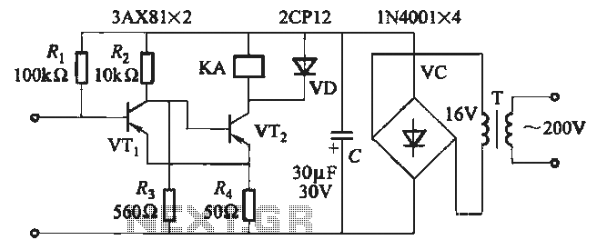
JB-22 transistor relay circuit
When the input is disconnected, the transistor VTi conducts, while VTz is in cutoff, causing relay KA to release. When the input is shorted, VTi is cut off, VTz conducts, and relay KA is activated.
In this circuit configuration, the operation...
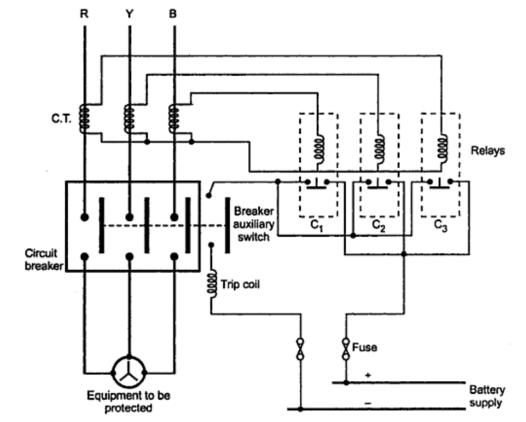
Trip Circuit of a Circuit Breaker
Consider a simplified circuit of a typical relay, which is usually part of a three-phase circuit with a complex contact system. The provided diagram illustrates a single-phase simplified circuit to clarify the basic operation of a relay. Part A represents...
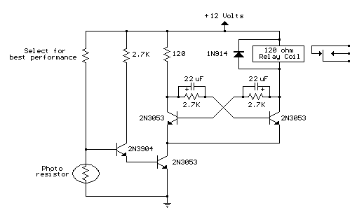
light activated relay
This circuit is similar to the previous one but incorporates a photoresistor to trigger the flip-flop instead of a push button. A bias resistor is placed in series with the photoresistor to ensure that adequate voltage is present at the...
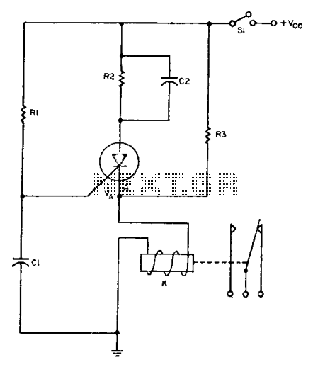
Relay driver
The relay operates for a specific duration, td, after power is applied, followed by an operating time, tc. The SCR activates when the voltage across capacitor Ci reaches a threshold voltage, VA. This action energizes the relay, which remains activated...
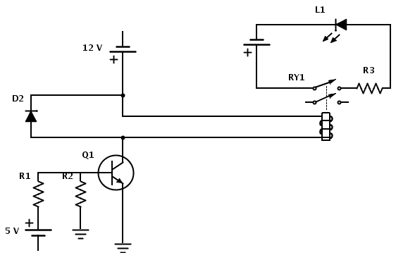
relay In a circuit being switched by an NPN transistor do power supply and input need the same ground
Create a circuit that enables the activation of a relay to control an LED. The relay operates at 12 V, while the available input voltage is 5 V. An NPN transistor will be utilized to switch the power to the...
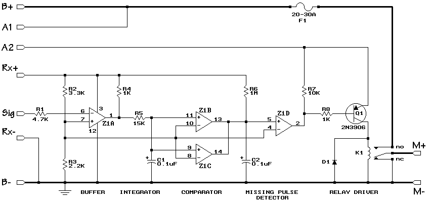
R/C On/Off Motor Controller with Brake
A relay-based on/off controller on the other hand can be very efficient. A typical relay has a contact resistance of 3 milliOhm. At 20A, this translates to a voltage drop of 0.06 volts, with a power loss of 1.2W. The...
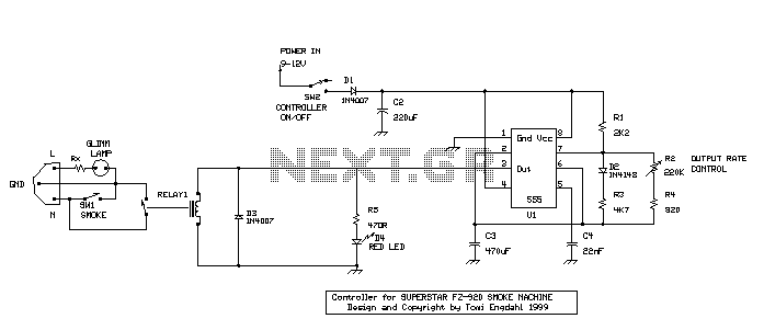
Disco Smoke controller
When the power is connected to the circuit by turning on SW2, RELAY1 gets energized for the time it takes to load C3 through R1 and R3. After that, the relay gets de-energized, and C3 gets discharged through R2 and...
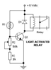
Light Dark switch activated relay circuits
This light-dark switch activated relay circuit schematic represents one of the simplest electronic circuits designed to activate other electronic devices based on light or darkness. It requires a single electronic relay and a few common components that are not critical....
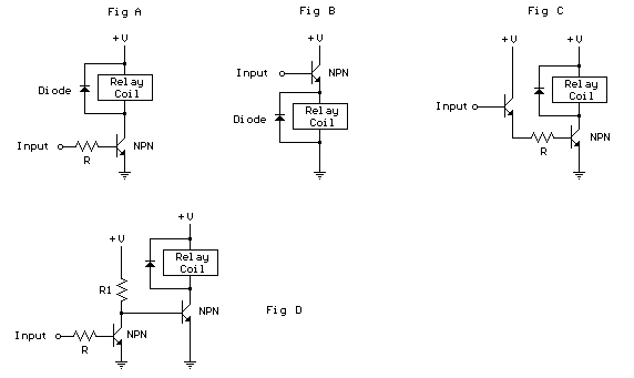
Controlling a relay with a digital logic level circuit
The schematic below illustrates four methods of controlling a relay with a digital logic signal. Figure A can be used in most cases where the relay coil requires 100 mA or less and the input current is 2 milliamps or...