


24 Second Shot Clock Circuit
#555 timer
#countdown
#debouncer
#astable multivibrator
#real time clock
#pulse input
#reset switch
#load switch
#pause switch
#synchronization
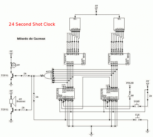
Description: To initiate the process, the LOAD switch and Reset switch must be pressed simultaneously within 24 seconds; otherwise, the countdown will commence from 99. A pulse input can be connected to a 555 astable multivibrator, but it must be calibrated for real-time clock functionality. The PAUSE switch requires a switch debouncer to ensure that the counter resumes normal operation when paused and then activated again. When the count reaches 00, the NOR gate will output a logic high (1), which will activate two transistors. This activation will cause a buzzer to sound and a light to illuminate. The two transistors will remain in the on state until both the LOAD switch and Reset switch are pressed. All components operate with a +5V power supply.
The described circuit operates as a countdown timer with specific functionalities tied to user inputs and component interactions. The initial setup requires the simultaneous pressing of the LOAD and Reset switches within a defined time frame. This condition is essential to prevent the timer from defaulting to a countdown from 99.
The integration of a 555 timer configured as an astable multivibrator allows for the generation of pulse signals, which can be calibrated for accurate timing. This calibration is crucial for ensuring that the timer reflects real-time accurately. The PAUSE switch is equipped with a debouncer circuit, which is necessary to prevent false triggering due to mechanical bouncing when the switch is pressed or released. This debouncing ensures the counter maintains its integrity during pause and resume operations.
Upon reaching a count of 00, a NOR gate is employed to provide a logic high output, which serves as a trigger for two transistors. These transistors act as switches that control the buzzer and light, signaling the end of the countdown. The output from the NOR gate effectively ensures that both transistors are activated simultaneously, providing a clear and audible indication of the countdown completion.
The design incorporates a power supply of +5V, which is sufficient for powering the 555 timer, NOR gate, transistors, and other associated components. The overall circuit design emphasizes reliability and user interaction, ensuring that the countdown timer functions as intended while providing feedback through visual and auditory signals. The use of transistors allows for efficient control of higher power devices such as buzzers and lights, ensuring that the circuit can be utilized in various applications requiring countdown functionalities.To start in 24 seconds; 24s LOAD SW and Reset SW should be push simultaneously. If not, the count will start in 99. Pulse input can be connected to 555 astable multivibrator but must be calibrated for real time clock. The PAUSE SW must have a Switch Debouncer so that the counter will count normal when counting is paused and then turn-on.
When the count reach 00, the NOR gate will have an output of logic1 that will turn on the two transistor. The buzzer will rung and light will turn on. The two transistors are continuously turn-on not until LOAD SW and Reset SW is push. All have a +5v power supply.
The described circuit operates as a countdown timer with specific functionalities tied to user inputs and component interactions. The initial setup requires the simultaneous pressing of the LOAD and Reset switches within a defined time frame. This condition is essential to prevent the timer from defaulting to a countdown from 99.
The integration of a 555 timer configured as an astable multivibrator allows for the generation of pulse signals, which can be calibrated for accurate timing. This calibration is crucial for ensuring that the timer reflects real-time accurately. The PAUSE switch is equipped with a debouncer circuit, which is necessary to prevent false triggering due to mechanical bouncing when the switch is pressed or released. This debouncing ensures the counter maintains its integrity during pause and resume operations.
Upon reaching a count of 00, a NOR gate is employed to provide a logic high output, which serves as a trigger for two transistors. These transistors act as switches that control the buzzer and light, signaling the end of the countdown. The output from the NOR gate effectively ensures that both transistors are activated simultaneously, providing a clear and audible indication of the countdown completion.
The design incorporates a power supply of +5V, which is sufficient for powering the 555 timer, NOR gate, transistors, and other associated components. The overall circuit design emphasizes reliability and user interaction, ensuring that the countdown timer functions as intended while providing feedback through visual and auditory signals. The use of transistors allows for efficient control of higher power devices such as buzzers and lights, ensuring that the circuit can be utilized in various applications requiring countdown functionalities.To start in 24 seconds; 24s LOAD SW and Reset SW should be push simultaneously. If not, the count will start in 99. Pulse input can be connected to 555 astable multivibrator but must be calibrated for real time clock. The PAUSE SW must have a Switch Debouncer so that the counter will count normal when counting is paused and then turn-on.
When the count reach 00, the NOR gate will have an output of logic1 that will turn on the two transistor. The buzzer will rung and light will turn on. The two transistors are continuously turn-on not until LOAD SW and Reset SW is push. All have a +5v power supply.
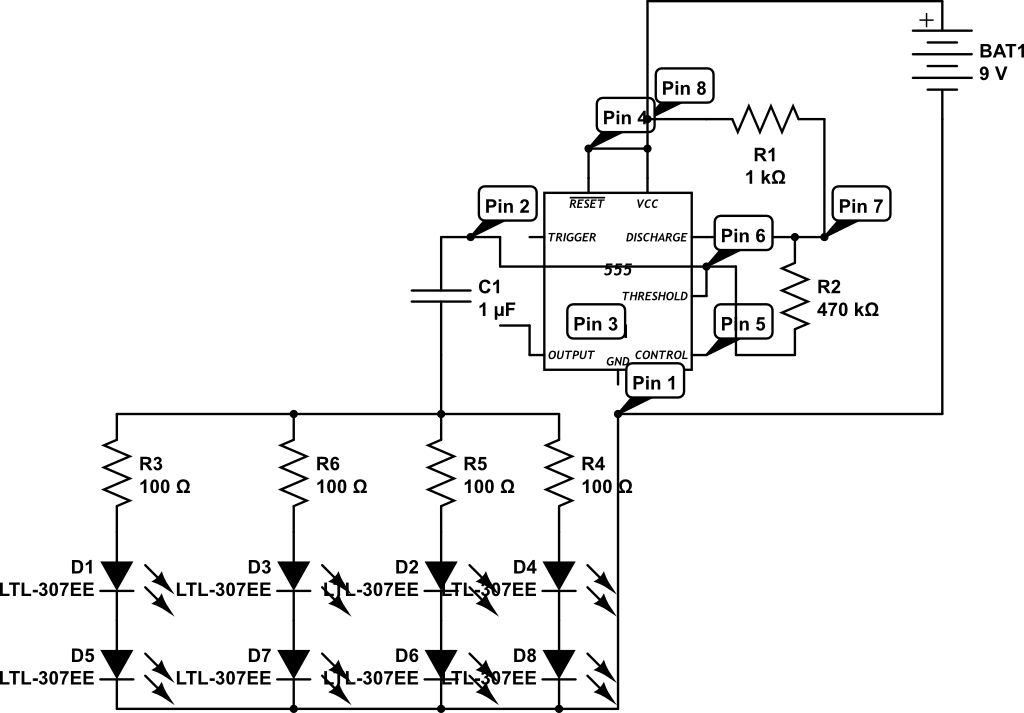
555 circuit for 8 leds flashing
LEDs are rated for a continuous current of only 30 mA, while this circuit operates them at approximately 50 mA. Although this is acceptable for low duty cycles with short pulses, the intended design has a high duty cycle. This...
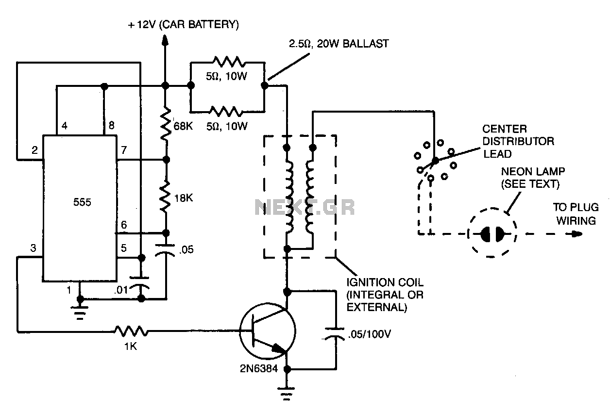
Automobile-ignition
The ignition substitute provides a constant power source for the ignition coil. Its frequency, 0.5-1.0 kHz, is that used by an 8-cylinder engine with an idling speed of 650 RPM, and the unit provides a rapid spark at a 17%...
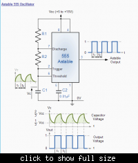
555 timer astable multivibrator
In the following astable multivibrator circuit, some sources state that the duty cycle is represented as d = (R1 + R2) / (R1 + 2 * R2), while other sources provide different information.
The astable multivibrator circuit is a type of...
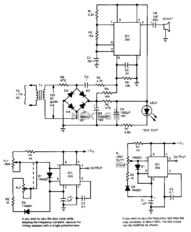
Ultrasonic-pest-repeller
This circuit utilizes a 555 timer integrated circuit (IC) configured as a square-wave generator. The base frequency is approximately 45 kHz, determined by the resistor values R1, R2, and the capacitor C1. The 45 kHz carrier frequency is frequency modulated...
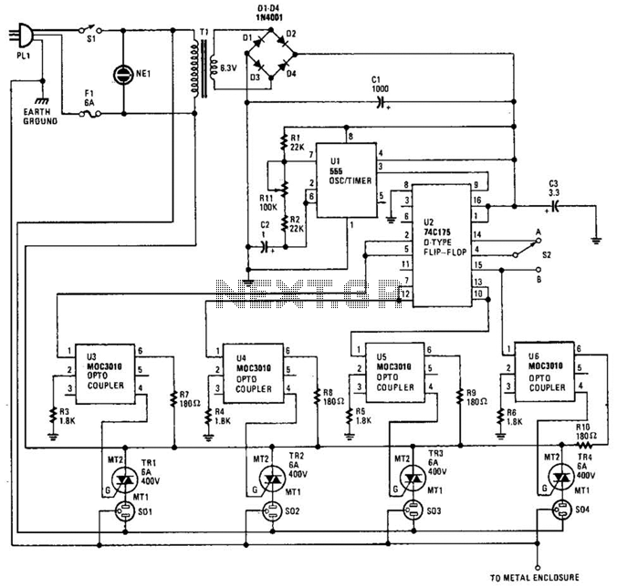
Holiday Light Sequencer Circuit
The integrated circuit U1 (a 555 oscillator/timer) is configured as a conventional pulse generator. The frequency of the pulse generator is adjusted using potentiometer R11. Resistor R2 limits the maximum frequency attainable. The output from the pulse generator is connected...
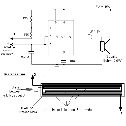
TV remote control blocker/jammer circuit diagram
This small device can be aimed at a television to jam the remote control signal. The circuit design is straightforward. A 555 timer is configured as an astable multivibrator operating at a frequency of approximately 38 kHz, which is the...
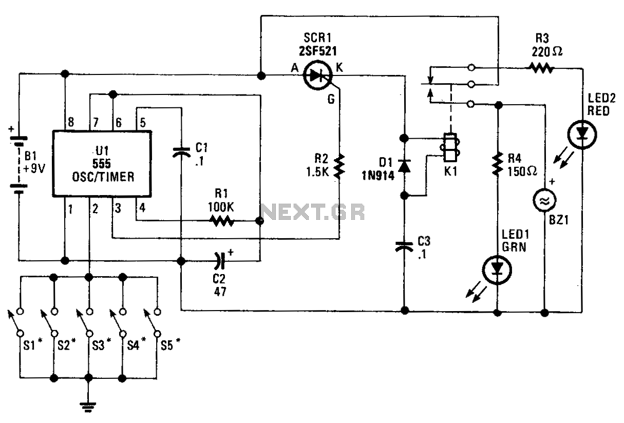
Burglar-alarm
The core component of the circuit is a 555 timer/oscillator, designated as U1, which is configured for monostable operation. The output from U1 at pin 3 is connected to the gate of SCR1. As long as switches S1 to S5,...
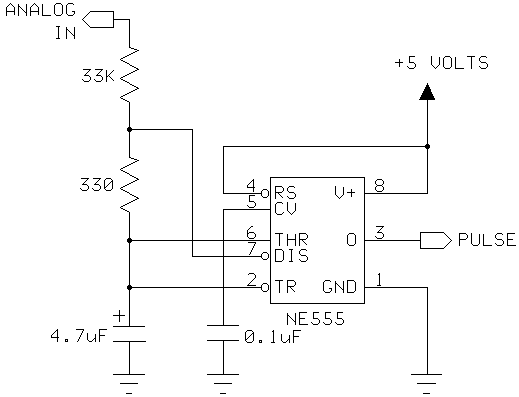
555 Timer as an A/D converter
I had a Basic Stamp project that needed to measure a nominal 12 volt battery, and I wanted a simple solution. This is the simplest I could come up with. The 555 timer will put out positive pulses. The pulse...
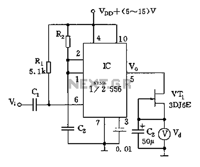
555 tachometer circuit diagram
The circuit utilizes switch contacts that are proportional to the speed pulse signal Vi. A differential signal is fed into the trigger side of an integrated circuit (IC), specifically a 555 timer configured in monostable mode (1/2 556), to create...