


555 as the core of a circuit diagram of proximity switch
#555 timer
#monostable
#trigger circuit
#proximity switch
#pulse generator
#timing circuit
#electronics
#sensor trigger
#VDD
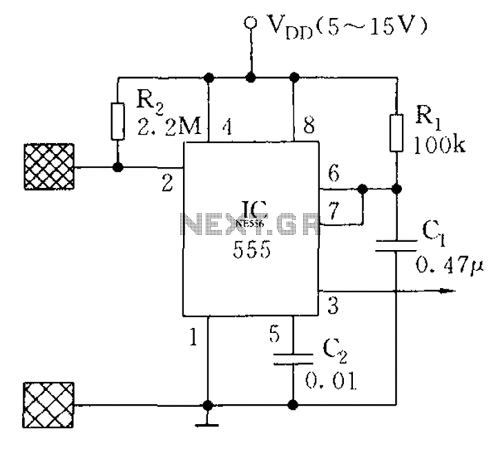
Description: The proximity switch using the 555 timer functions as a monostable trigger circuit. The trigger pin (Pin 2) of the 555 timer is connected through a large resistor (R2) to the positive supply voltage (VDD) and is in a standby state, awaiting a trigger condition. When a body approaches or touches the metal plate electrodes, the sensor signal activates the 555 timer, resulting in a one-shot pulse output. Capacitor C2 is used for filtering interference. This circuit is suitable for applications in electrical appliances, toys, or alarm systems.
The circuit utilizes the 555 timer IC, a versatile and widely used component in various electronic applications. In the monostable configuration, the 555 timer generates a single output pulse of a specified duration in response to an external trigger. The duration of the pulse is determined by the resistor (R1) and capacitor (C1) values, following the formula T = 1.1 * R1 * C1, where T is the pulse width.
In this design, R2 serves to pull the trigger pin (Pin 2) high, ensuring that the circuit remains inactive until a triggering event occurs. The metal plate electrodes act as the sensing mechanism, detecting the presence of a nearby object, such as a hand or body. Upon detection, the electrodes generate a low signal that is fed to Pin 2, causing the 555 timer to switch from its stable state to an active state, producing a high output pulse.
Capacitor C2 plays a crucial role in filtering out any noise or interference that may affect the signal integrity. By smoothing out voltage fluctuations, C2 helps to ensure that the output pulse is clean and reliable. This feature is particularly important in environments where electromagnetic interference may be present.
The output from the 555 timer can be used to control various devices, such as relays, LEDs, or other components, enabling the circuit to function as an activation mechanism for electrical appliances, toys, or alarm systems. This flexibility makes the proximity switch circuit a valuable addition to many electronic projects, providing a simple yet effective means of detecting proximity and triggering actions accordingly. As shown, the proximity switch 555 as the core component monostable trigger circuit. 555 Trigger Pin 2 through the large resistance R2 connected to VDD, is waiting for a trigge r condition. When the body close to or touch the metal plate electrodes, since the sensor signal 555 is triggered, a one-shot pulse output. C2 filtering for interference. The circuit can be used for electrical appliances, toys or alarm circuit.
The circuit utilizes the 555 timer IC, a versatile and widely used component in various electronic applications. In the monostable configuration, the 555 timer generates a single output pulse of a specified duration in response to an external trigger. The duration of the pulse is determined by the resistor (R1) and capacitor (C1) values, following the formula T = 1.1 * R1 * C1, where T is the pulse width.
In this design, R2 serves to pull the trigger pin (Pin 2) high, ensuring that the circuit remains inactive until a triggering event occurs. The metal plate electrodes act as the sensing mechanism, detecting the presence of a nearby object, such as a hand or body. Upon detection, the electrodes generate a low signal that is fed to Pin 2, causing the 555 timer to switch from its stable state to an active state, producing a high output pulse.
Capacitor C2 plays a crucial role in filtering out any noise or interference that may affect the signal integrity. By smoothing out voltage fluctuations, C2 helps to ensure that the output pulse is clean and reliable. This feature is particularly important in environments where electromagnetic interference may be present.
The output from the 555 timer can be used to control various devices, such as relays, LEDs, or other components, enabling the circuit to function as an activation mechanism for electrical appliances, toys, or alarm systems. This flexibility makes the proximity switch circuit a valuable addition to many electronic projects, providing a simple yet effective means of detecting proximity and triggering actions accordingly. As shown, the proximity switch 555 as the core component monostable trigger circuit. 555 Trigger Pin 2 through the large resistance R2 connected to VDD, is waiting for a trigge r condition. When the body close to or touch the metal plate electrodes, since the sensor signal 555 is triggered, a one-shot pulse output. C2 filtering for interference. The circuit can be used for electrical appliances, toys or alarm circuit.
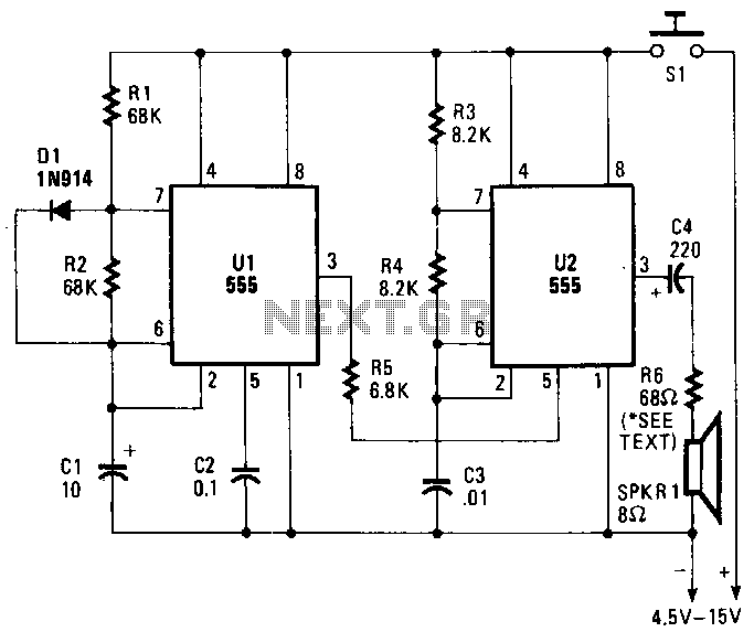
Hee-haw-slren
A pair of timer integrated circuits (ICs) form the core of a circuit designed to simulate the distinctive warbling sound of a British police siren. One of the 555 timers, designated as U2, is configured as an astable multivibrator that...
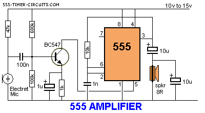
simple 555 amplifier
The 555 timer can function as an amplifier, operating similarly to pulse-width modulation. The component values lead the 555 to oscillate at approximately 66 kHz, a frequency to which the speaker does not respond. Instead, the speaker reacts to the...
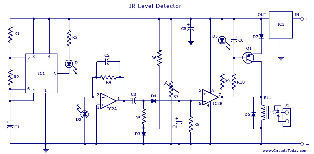
555 Timer IC For IR Detector Circuit
The circuit illustrates the use of a 555 Timer IC in an infrared (IR) detector configuration. It features a duty cycle of 0.8 milliseconds, a frequency of 120 Hz, and a peak current of 300 mA.
The 555 Timer IC is...
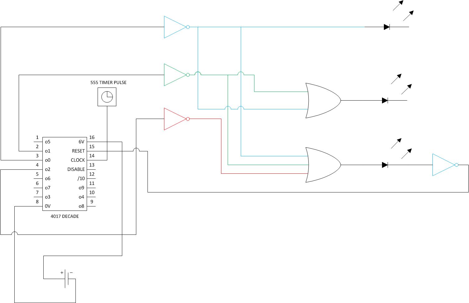
555 How can I make a 15 minute egg timer circuit
The goal is to create a timer activated by a button press, which will light three LEDs. After each 5-minute segment, one LED should turn off. After 15 minutes, a solenoid should ring a bell once. The individual has a...
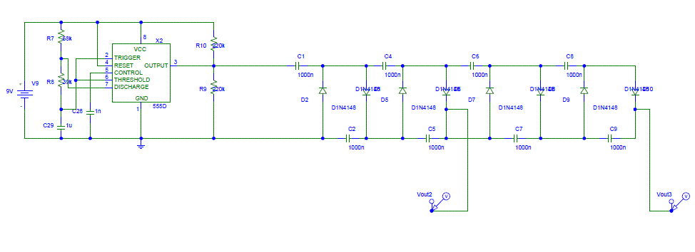
switching between parts circuit pulse input
This circuit operates as a 9V DC power source supplying a 555 timer to generate a square wave. The output is then processed through a Half-Wave Series Multiplier (Villard Cascade) to achieve a high voltage DC output. The goal is...
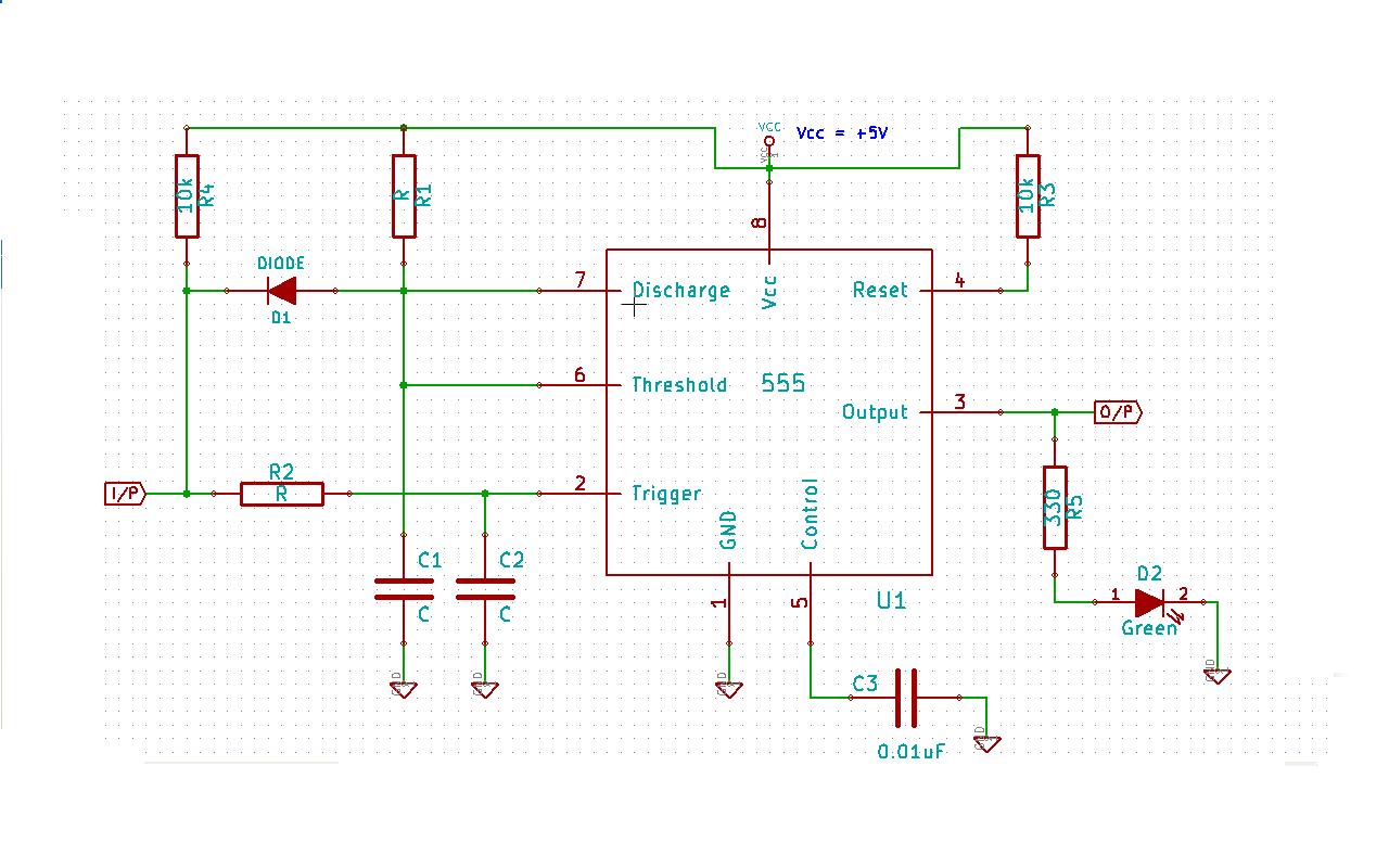
digital logic purpose of diode in this 555 timer application
Create a 555 timer-based circuit where the output pin of the 555 timer is held low by default when powered on, and the input pin is held high at power on. The main requirement is that the output pin should...
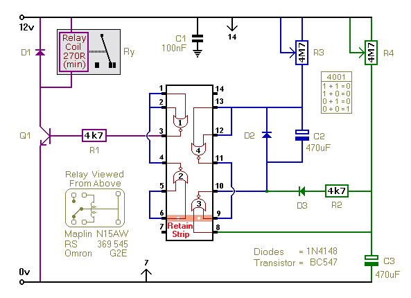
A Repeating Timer Circuit No.7
This timer utilizes a basic monostable circuit. The duration for which the relay remains energized, referred to as the ON period, is regulated by the resistor R3 and capacitor C2. Conversely, the duration for which the relay remains de-energized, known...
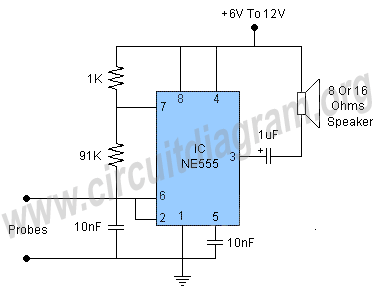
water level alarm using 555 ic
This water level alarm circuit can be utilized as a water level indicator to monitor the desired water level in various applications, such as tanks, swimming pools, or any location where water is stored. The circuit is constructed using a...
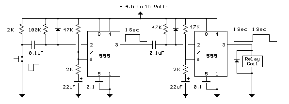
Generating a Delayed Pulse Using The 555 Timer circuit
The circuit below demonstrates the generation of a single positive pulse that is delayed in relation to the trigger input time. It is similar to a previously described circuit but utilizes two stages, allowing for control over both the pulse...