


American Police Car Siren by IC 555
#555 timer
#siren
#astable
#pulse generator
#audio effect
#transistor
#ramp waveform
#low frequency
#alarm tone
#police car
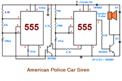
Description: The second circuit simulates the siren of an American police car. It utilizes two 555 timers. The 555 timer on the right is configured as an alarm tone generator, while the second 555 timer on the left operates as a low-frequency astable timer, generating a ramp waveform of approximately 6 seconds. This waveform is buffered by a transistor and is used to frequency modulate the tone generator. The transistor serves to amplify the signal sent to the speaker.
The circuit comprises two 555 timer integrated circuits (ICs), each serving distinct functions to replicate the sound of a police siren. The first timer, positioned on the right, is set up in a monostable mode to produce a square wave tone, which simulates the alarm sound. This timer's output frequency is adjustable, allowing for variations in the siren tone, which is essential for realism.
The second timer, located on the left, operates in astable mode, generating a continuous ramp waveform with a period of approximately 6 seconds. This waveform is crucial for modulating the frequency of the tone produced by the first timer. The modulation creates a more dynamic and realistic siren effect, mimicking the varying pitch heard in actual police sirens.
A transistor is integrated into the circuit to buffer the output from the second timer. This arrangement strengthens the signal, ensuring that it is sufficiently robust to drive a speaker. The use of a transistor not only enhances the output signal but also provides isolation between the timer circuits and the speaker, preventing potential damage to the timers from load variations.
The overall design of the circuit emphasizes simplicity while effectively achieving the desired sound output. The use of common components such as the 555 timer and a transistor makes the circuit accessible for hobbyists and educational purposes, providing a practical example of sound synthesis using basic electronic components.The second circuit simulates the siren of an American police car. It uses two 555 timers in the circuit. The 555 on the right is wired as an alarm tone generator and the second 555 timer on the left is wired as a low frequency astable timer which generates a ramp waveform of about 6 seconds that is buffered by the transistor and again used to freq uency modulate the tone generator. The transistor is used to help strengthen the signal to the speaker
The circuit comprises two 555 timer integrated circuits (ICs), each serving distinct functions to replicate the sound of a police siren. The first timer, positioned on the right, is set up in a monostable mode to produce a square wave tone, which simulates the alarm sound. This timer's output frequency is adjustable, allowing for variations in the siren tone, which is essential for realism.
The second timer, located on the left, operates in astable mode, generating a continuous ramp waveform with a period of approximately 6 seconds. This waveform is crucial for modulating the frequency of the tone produced by the first timer. The modulation creates a more dynamic and realistic siren effect, mimicking the varying pitch heard in actual police sirens.
A transistor is integrated into the circuit to buffer the output from the second timer. This arrangement strengthens the signal, ensuring that it is sufficiently robust to drive a speaker. The use of a transistor not only enhances the output signal but also provides isolation between the timer circuits and the speaker, preventing potential damage to the timers from load variations.
The overall design of the circuit emphasizes simplicity while effectively achieving the desired sound output. The use of common components such as the 555 timer and a transistor makes the circuit accessible for hobbyists and educational purposes, providing a practical example of sound synthesis using basic electronic components.The second circuit simulates the siren of an American police car. It uses two 555 timers in the circuit. The 555 on the right is wired as an alarm tone generator and the second 555 timer on the left is wired as a low frequency astable timer which generates a ramp waveform of about 6 seconds that is buffered by the transistor and again used to freq uency modulate the tone generator. The transistor is used to help strengthen the signal to the speaker
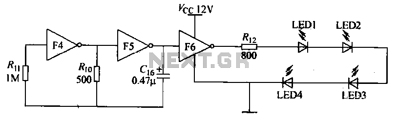
Low frequency oscillation circuit
Gates F4, F5, and F6 together form a low-frequency oscillator that drives high-brightness light-emitting diode (LED) flashes. The light-emitting diodes may be arranged around the booth seat for decorative purposes. The automatic referral machine is used prior to operation to...
monitor an input pulse train
This circuit functions as a missing pulse detector, utilized in the General Purpose Controller Board with Basic Stamp 1. It monitors an input pulse train, and when a pulse is missed, the output of the 555 timer switches to a...
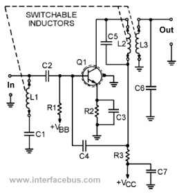
Transistor Circuits
This page presents several transistor circuits that are not commonly found on other pages due to the absence of a specific topic. These circuits, however, illustrate particular points but lack detailed descriptions. An example of an RF amplifier circuit using...
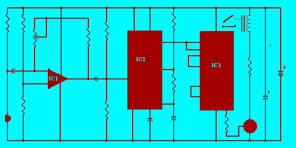
Clap switch using timer 555
A single hand clap will be picked up by the electric mic which is coupled through C1 into the op amp IC1. The output of IC1 triggers the 555 IC timer IC2 which is configured as a monostable multivibrator. The...
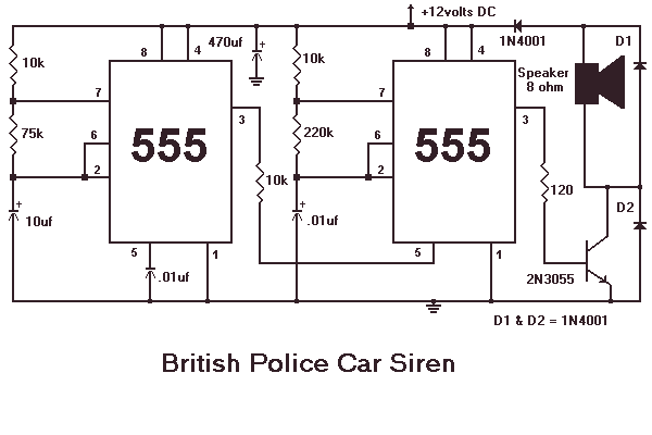
Siren Circuits using timer 555
This month I am making 3 different types of siren circuits based on the 555 timer. The first circuit simulates the siren of a British police car. It uses two 555 timers in the circuit. The 555 on the right...
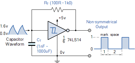
Non-standard 555 Astable Multivibrator
A square wave generator with a variable frequency and a 50% duty cycle is required. While the 555 timer is a common choice, the standard astable multivibrator configuration alters the duty cycle when the frequency is adjusted. A circuit found...
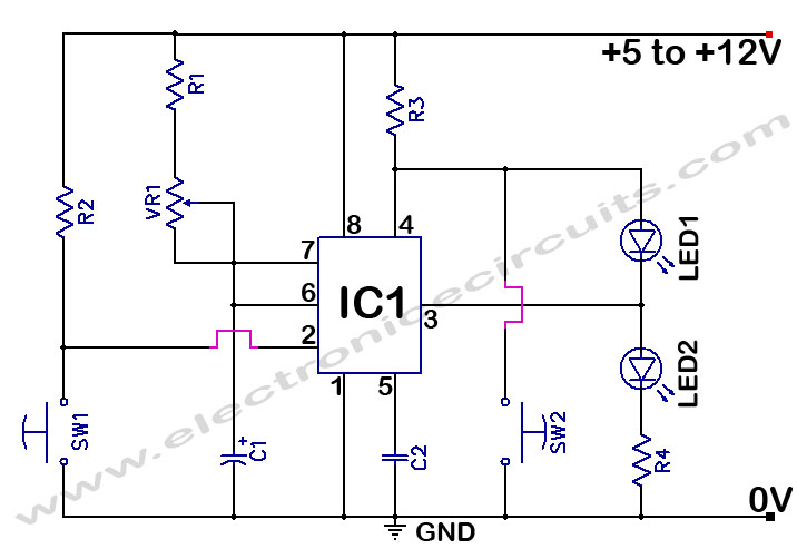
555 Timer Time Delay Circuit
The 555 Timer Time Delay Circuit uses LEDs to visually indicate the status of the circuit at any moment. The operation begins when the reset switch, SW2, is activated.
The 555 Timer is a versatile integrated circuit widely used for generating...
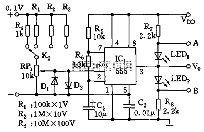
555 meter circuit diagram of a DC voltage
The control terminal at 5 feet and the threshold end at 6 feet represent two internal input voltage comparators. As long as the voltage at 6 feet exceeds the voltage at 5 feet by 5 mV, the 555 timer will...
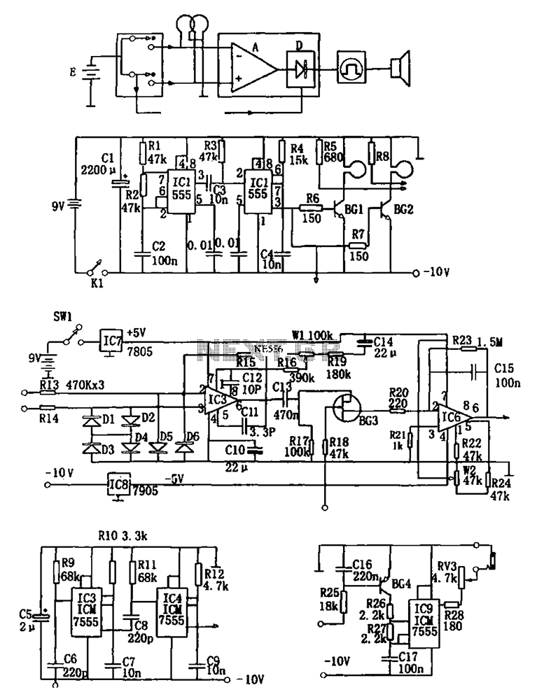
555 double coil metal detectors
The figure illustrates a double coil metal detector circuit, which consists of a probe, a transmitter, a receiver, a timer, sound transmitters, and other components. The transmitter circuit, depicted in (b), is composed of a multivibrator (IC1, R1, R2, C2)...