


Automatic School Bell Circuit PCB
#school bell
#timer
#automation
#PCB
#periodic signal
#control circuit
#educational
#scheduling
#momentary switch
#bell ringing
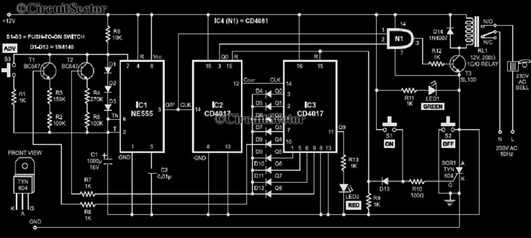
Description: A school operates with a total of eight periods, each lasting 45 minutes, and includes a 30-minute lunch break following the fourth period. A bell is used to signal the start of each class, the end of each period, and the extension of the lunch break. To initiate the first period, a peon must briefly press switch S1. The 555 timer integrated circuit (IC) is configured as an astable multivibrator, producing clock output pulses that are fed into the CD4017 integrated circuit (IC2). This IC increases the timing intervals of the 555 timer (IC1) by a factor of ten, generating clock pulses for IC3 every 45 minutes or every 30 minutes during lunch. While classes are in session, the outputs of IC3 activate transistors T1 and T2 through diodes D4 to D12.
The electronic circuit described consists of a timing mechanism designed to manage the schedule of a school day. The 555 timer is set up in astable mode, which allows it to continuously oscillate and generate a square wave output. The frequency of this output can be adjusted by selecting appropriate resistors and capacitors in the circuit. In this application, the output pulse from the 555 timer is fed into a CD4017 decade counter, which counts the pulses and provides outputs at specific counts.
The CD4017 is a popular decade counter that has ten output pins, each corresponding to a count from 0 to 9. In this configuration, the output of the CD4017 is used to trigger the next stage of the circuit, which is the timing mechanism for the class periods and lunch breaks. The increase of the timing periods by a factor of ten ensures that the output from the 555 timer can be effectively utilized to manage longer intervals, specifically designed to match the school schedule of 45-minute class periods and a 30-minute lunch break.
The clock pulses are generated such that after the 555 timer completes its cycle, the CD4017 outputs will activate transistors T1 and T2. These transistors act as switches that control the power to the bell system. The diodes D4 to D12 are included in the circuit to prevent backflow of current and to ensure that the transistors are driven correctly by the outputs of IC3. This arrangement ensures that the bell rings at the appropriate times, signaling the start and end of each class period and the lunch break, thereby maintaining the school's schedule efficiently.
Overall, this circuit provides a reliable and automated method to manage the timing of a school day, improving the efficiency of transitions between periods and ensuring that students and staff are informed of schedule changes through an audible signal.Consider that a school has a total of eight periods with a lunch break after the fourth period. Each period is 45 minutes long, while the duration of the lunch break is 30 minutes. The bell will be ringed to start the class, end of each period, extension at lunch break etc. To ring the bell to start first period, the peon needs to momentarily pres s switch S1. The 555 timer IC is configured as an astable multivibrator whose clock output pulses are fed to the CD 4017 IC. IC2 increases the time periods of IC1 (4. 5 and 3 minutes) by ten times to provide a clock pulse to IC3 every 45 minutes or after 30 minutes, respectively.
When the class periods are going on, the outputs of IC3 switch on transistors T1 and T2 via diodes D4 through D12.
The electronic circuit described consists of a timing mechanism designed to manage the schedule of a school day. The 555 timer is set up in astable mode, which allows it to continuously oscillate and generate a square wave output. The frequency of this output can be adjusted by selecting appropriate resistors and capacitors in the circuit. In this application, the output pulse from the 555 timer is fed into a CD4017 decade counter, which counts the pulses and provides outputs at specific counts.
The CD4017 is a popular decade counter that has ten output pins, each corresponding to a count from 0 to 9. In this configuration, the output of the CD4017 is used to trigger the next stage of the circuit, which is the timing mechanism for the class periods and lunch breaks. The increase of the timing periods by a factor of ten ensures that the output from the 555 timer can be effectively utilized to manage longer intervals, specifically designed to match the school schedule of 45-minute class periods and a 30-minute lunch break.
The clock pulses are generated such that after the 555 timer completes its cycle, the CD4017 outputs will activate transistors T1 and T2. These transistors act as switches that control the power to the bell system. The diodes D4 to D12 are included in the circuit to prevent backflow of current and to ensure that the transistors are driven correctly by the outputs of IC3. This arrangement ensures that the bell rings at the appropriate times, signaling the start and end of each class period and the lunch break, thereby maintaining the school's schedule efficiently.
Overall, this circuit provides a reliable and automated method to manage the timing of a school day, improving the efficiency of transitions between periods and ensuring that students and staff are informed of schedule changes through an audible signal.Consider that a school has a total of eight periods with a lunch break after the fourth period. Each period is 45 minutes long, while the duration of the lunch break is 30 minutes. The bell will be ringed to start the class, end of each period, extension at lunch break etc. To ring the bell to start first period, the peon needs to momentarily pres s switch S1. The 555 timer IC is configured as an astable multivibrator whose clock output pulses are fed to the CD 4017 IC. IC2 increases the time periods of IC1 (4. 5 and 3 minutes) by ten times to provide a clock pulse to IC3 every 45 minutes or after 30 minutes, respectively.
When the class periods are going on, the outputs of IC3 switch on transistors T1 and T2 via diodes D4 through D12.
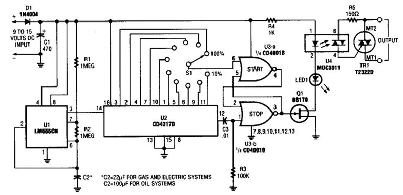
Furnace Fuel Miser Circuit
A timer (LM555CN) and decode counter are utilized to generate duty cycles ranging from 10% to 100% for controlling the operational time of a heating system. V2 operates as a decode counter that can be adjusted for duty cycles between...

repeating interval timer
This circuit features an adjustable output timer that can re-trigger at specified intervals. The output duration can range from a fraction of a second to over half an hour, with the ability to repeat at consistent intervals from seconds to...
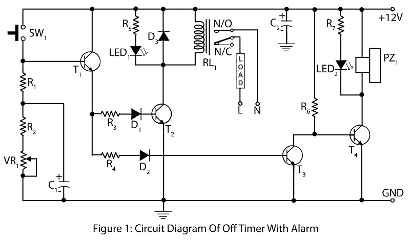
Off timer with alarm with description
An off timer with an alarm is a straightforward project designed to indicate the end of a specified time period. The circuit utilizes four transistors. It includes a circuit diagram along with a parts list and a description of the...
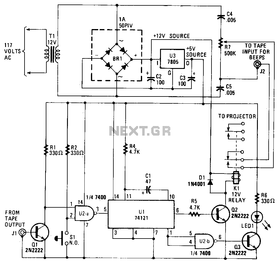
Slide-timer
This circuit records commentary and music on one track of a tape while placing beeps that signal slide changes on another track. The gate U2a triggers U1, which is configured as a timer that generates a pulse each time it...
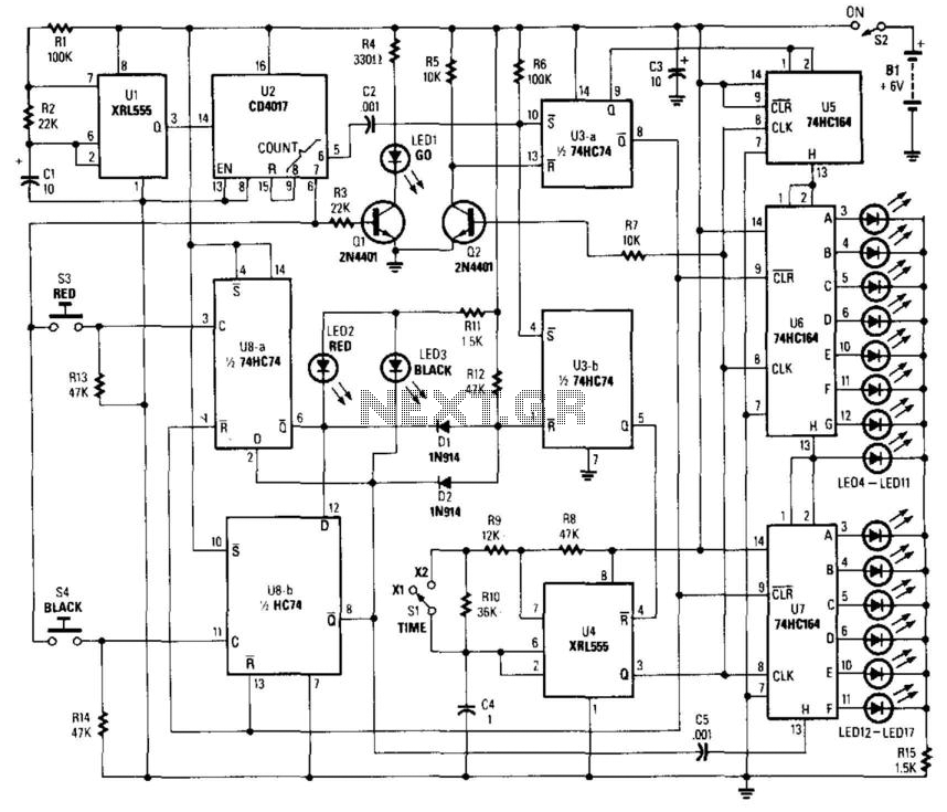
Reaction Timer
This circuit utilizes a timer to produce pulses at a 5-ms clock rate. The pulses are sequentially shifted into a shift register, illuminating an LED. An auxiliary timer generates one pulse per second to activate the "go" LED and initiate...
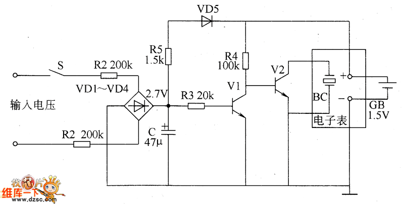
Cumulative timer circuit diagram
The cumulative timer circuit comprises resistor R1 and an internal crystal oscillator, represented in a chart. Resistors R1 and R2 are metal film types, while resistors R3 to R5 are rated at 1/8W and also of the metal film variety....
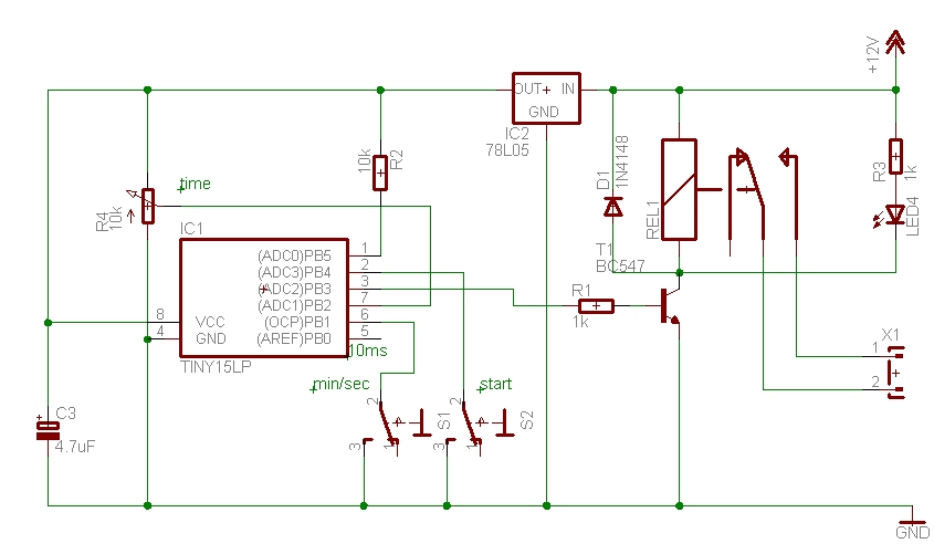
Timer circuit
The time can be set using a potentiometer ranging from 1 minute to 1023 minutes, approximately 17 hours. A pushbutton initiates the timing process, activates a relay, and the timer will deactivate the relay once the set time has elapsed....
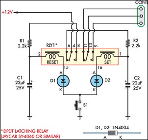
Momentary Switch Teamed With Latching Relay
This circuit enables an SPST momentary pushbutton to function as a push-on push-off switch by utilizing a DPDT latching (bi-stable) relay. It was designed to allow a single pushbutton switch on the dashboard of a vintage car to provide a...
bedside lamp timer schematics
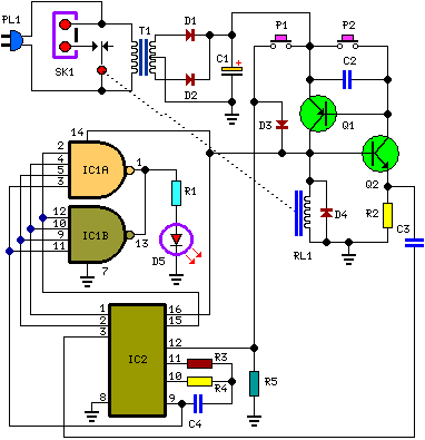
Q1 and Q2 create an ALL-ON ALL-OFF circuit that, when in the off state, draws negligible current. P1 initiates the circuit, activating the relay and powering the two integrated circuits (ICs). The lamp is energized through the relay switch, and...