


DC flasher with adjustable on and off time
#DC flasher
#adjustable timing
#flip-flop
#programmable unijunction transistor
#PUT
#pulse generator
#timer circuit
#flashing circuit

Description: This circuit utilizes a power flip-flop and programmable unijunction transistor (PUT) to obtain adjustable on and off times.
The circuit design incorporates a power flip-flop, which serves as a bistable multivibrator capable of maintaining a stable output state until triggered to switch. The power flip-flop is particularly advantageous in applications requiring low power consumption while providing reliable switching capabilities. The output states of the flip-flop can be toggled by applying a control voltage to its input, allowing the circuit to effectively control the timing of the output signal.
In conjunction with the power flip-flop, a programmable unijunction transistor (PUT) is employed to facilitate the timing mechanism. The PUT is a three-terminal device that can be programmed to trigger at a specific voltage level, making it suitable for generating precise timing intervals. By adjusting the gate voltage of the PUT, the on and off times can be finely tuned according to the application requirements.
The circuit configuration typically involves connecting the output of the power flip-flop to the gate of the PUT. When the flip-flop transitions states, it triggers the PUT, which subsequently controls the flow of current through the load. The timing characteristics of the circuit can be adjusted by varying the resistance and capacitance in the timing network associated with the PUT, allowing for a wide range of adjustable on and off durations.
This combination of a power flip-flop and a programmable unijunction transistor provides a flexible and efficient solution for applications that require precise control over timing sequences, such as in timing circuits, pulse generators, and various automation systems. The ability to adjust the timing parameters enhances the versatility of the circuit, making it suitable for a broad spectrum of electronic applications.This circuit utilizes a power flip-flop and programmable unijunction (PUT) to obtain adjustable on and off times.
The circuit design incorporates a power flip-flop, which serves as a bistable multivibrator capable of maintaining a stable output state until triggered to switch. The power flip-flop is particularly advantageous in applications requiring low power consumption while providing reliable switching capabilities. The output states of the flip-flop can be toggled by applying a control voltage to its input, allowing the circuit to effectively control the timing of the output signal.
In conjunction with the power flip-flop, a programmable unijunction transistor (PUT) is employed to facilitate the timing mechanism. The PUT is a three-terminal device that can be programmed to trigger at a specific voltage level, making it suitable for generating precise timing intervals. By adjusting the gate voltage of the PUT, the on and off times can be finely tuned according to the application requirements.
The circuit configuration typically involves connecting the output of the power flip-flop to the gate of the PUT. When the flip-flop transitions states, it triggers the PUT, which subsequently controls the flow of current through the load. The timing characteristics of the circuit can be adjusted by varying the resistance and capacitance in the timing network associated with the PUT, allowing for a wide range of adjustable on and off durations.
This combination of a power flip-flop and a programmable unijunction transistor provides a flexible and efficient solution for applications that require precise control over timing sequences, such as in timing circuits, pulse generators, and various automation systems. The ability to adjust the timing parameters enhances the versatility of the circuit, making it suitable for a broad spectrum of electronic applications.This circuit utilizes a power flip-flop and programmable unijunction (PUT) to obtain adjustable on and off times.
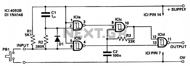
Delayed pulse generator
The circuit provides independent control of the initial delay and pulse rate. ICIc functions as a pulse generator, with its operation inhibited by the normally low output of ICla. When the circuit input transitions to low (e.g., when pressing PB1),...
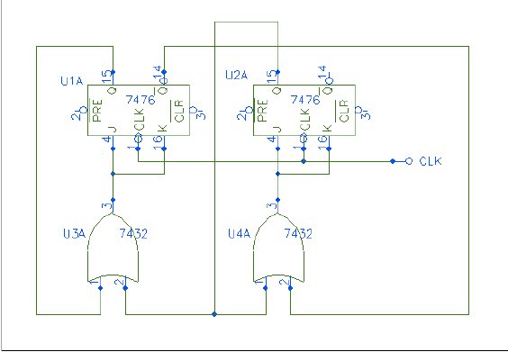
flipflop What happens when theres no specific input variable on a logic diagram using a JK flip flop
Q1 and Q2 form a table. On the left side, list the four possible states of Q1 and Q2; on the right side, write the values that Q1 and Q2 will assume after the next clock pulse. The table will...
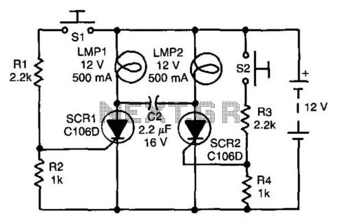
Flip-Flop Independent Lamp Driver
Assume first that SCR1 is on and SCR2 is off, allowing capacitor CI to be fully charged, with its LMP2 end positive. The state of the circuit can be altered by pressing switch S2. When SCR2 turns on, it capacitively...
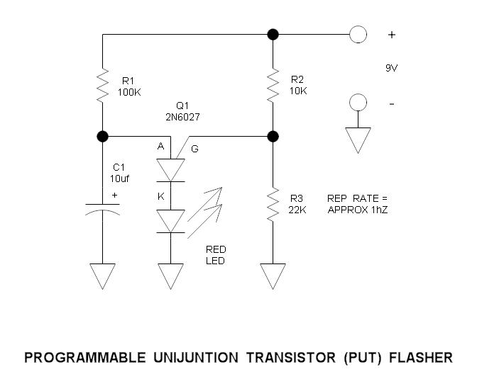
Programmable Unijunction Transistor (PUT) Flasher Circuit
This is a simple circuit that illustrates the function of the programmable unijunction transistor. It can be quickly wired on a proto-board.
The circuit utilizes a programmable unijunction transistor (PUT) to demonstrate its operation as an oscillator. The PUT, which is...
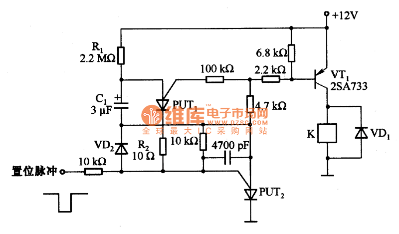
Improved one-shot timer circuit composed of 2 PUT
Figure 1 illustrates an enhanced trigger timing circuit that utilizes two Programmable Unijunction Transistors (PUTs). When a set signal is applied, the circuit is activated, causing transistor VT1 to enter the conduction state and energizing relay K. This action simultaneously...
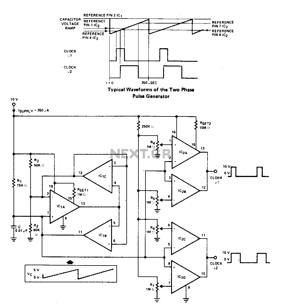
Versatile two-phase pulse generator
A two-phase clock generator utilizes two L161 integrated circuits to produce pulses with adjustable widths and phase relationships. Additionally, a ramp generator supplies input to two variable window comparators, which are configured using IC2A-IC2B and IC2C-IC2D, respectively.
The two-phase clock generator...
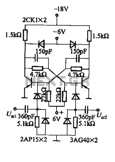
Practical flip-flop circuit
A flip-flop circuit with a memory function for pulse signals. It features two stable states: one where transistor VTi is off and VTZ is conducting, and another where VTi is conducting and VT2 is off. An external signal is sufficient...
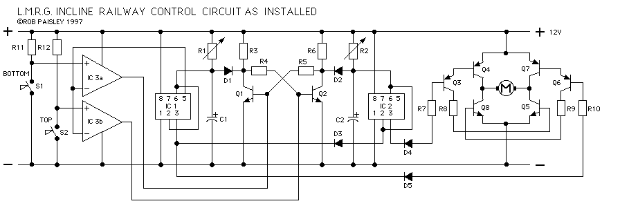
Incline Railway Project
The drawings and photos below are for an operating incline railway that was built by the London Model Railroad Group for its O scale model railway club located at London, Ontario, Canada. This is a single car model loosely based...
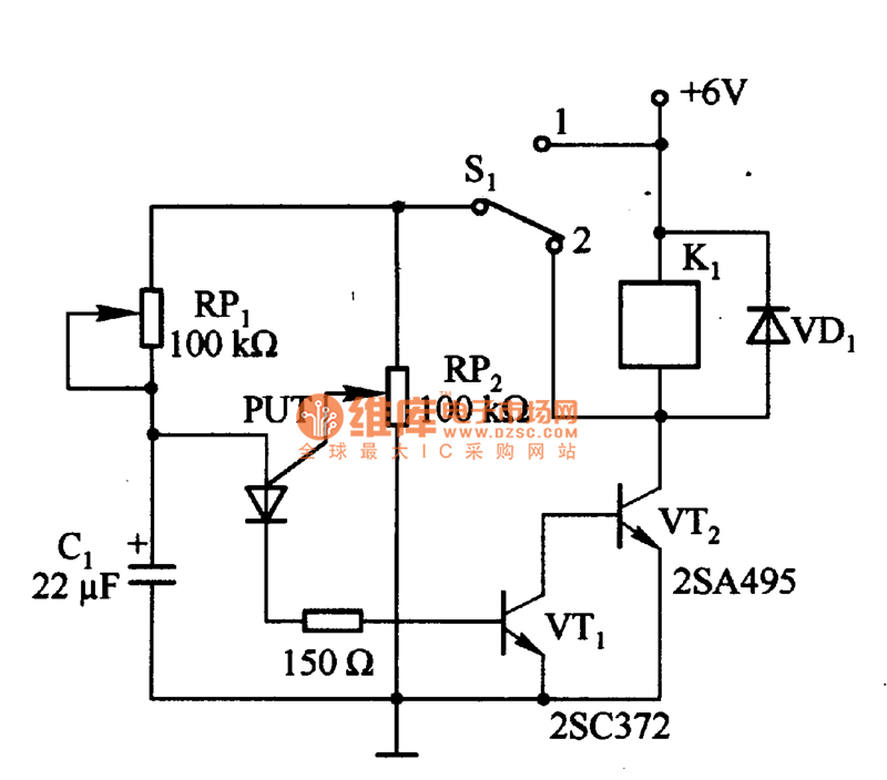
Automatic interval timer circuit composed of PUT
Figure 1 consists of a Programmable Unijunction Transistor (PUT) and an automatic interval timer circuit. In this circuit, the PUT serves as the oscillator. The switch S1 is used to toggle between interval timing and automatic timing modes. When S1...