


Generation of 1-Sec Pulses Spaced 5-Sec Apart
#NE556
#dual-timer
#pulse generator
#1Hz pulses
#5-second spacing
#manual control
#automatic control
#timing circuit
#signal generation
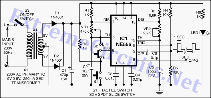
Description: This circuit utilizes a dual-timer NE556 to generate 1Hz pulses spaced 5 seconds apart, with the option for manual or automatic operation. The NE556 integrated circuit (IC) consists of two independent timers.
The NE556 timer is a versatile device that combines two 555 timer circuits into a single package, allowing for various timing applications. In this particular configuration, it is set up to produce a square wave output at a frequency of 1Hz. This is achieved by configuring one of the timers in astable mode, where the timing components, specifically resistors and capacitors, determine the frequency and duty cycle of the output pulse.
To create 1Hz pulses, the circuit requires specific resistor and capacitor values calculated using the formula for the frequency of an astable multivibrator. The frequency (f) is given by the equation:
f = 1.44 / ((R1 + 2*R2) * C)
Where R1 and R2 are the resistances connected to the discharge and threshold pins of the timer, and C is the capacitance connected to the timing capacitor pin. For a frequency of 1Hz, appropriate values for R1, R2, and C must be selected to meet this requirement while ensuring the desired pulse width.
The NE556 allows for both manual and automatic operation of the timing circuit. In manual mode, a switch can be integrated to start and stop the pulse generation at the user's discretion. In automatic mode, the circuit can continuously generate pulses without user intervention, making it suitable for applications such as LED blinking, clock generation, or timing applications in various electronic devices.
The output from the NE556 can be connected to various loads, such as LEDs or relays, to indicate the timing intervals visually or to control other circuits. Proper decoupling capacitors should be placed close to the power supply pins of the NE556 to ensure stable operation and minimize noise.
Overall, this circuit design using the NE556 timer provides a simple yet effective solution for generating timed pulses in a variety of electronic applications.This circuit using a dual-timer NE556 can produce 1Hz pulses spaced 5 seconds apart, either manually or automatically. IC NE556 comprises two independent..
The NE556 timer is a versatile device that combines two 555 timer circuits into a single package, allowing for various timing applications. In this particular configuration, it is set up to produce a square wave output at a frequency of 1Hz. This is achieved by configuring one of the timers in astable mode, where the timing components, specifically resistors and capacitors, determine the frequency and duty cycle of the output pulse.
To create 1Hz pulses, the circuit requires specific resistor and capacitor values calculated using the formula for the frequency of an astable multivibrator. The frequency (f) is given by the equation:
f = 1.44 / ((R1 + 2*R2) * C)
Where R1 and R2 are the resistances connected to the discharge and threshold pins of the timer, and C is the capacitance connected to the timing capacitor pin. For a frequency of 1Hz, appropriate values for R1, R2, and C must be selected to meet this requirement while ensuring the desired pulse width.
The NE556 allows for both manual and automatic operation of the timing circuit. In manual mode, a switch can be integrated to start and stop the pulse generation at the user's discretion. In automatic mode, the circuit can continuously generate pulses without user intervention, making it suitable for applications such as LED blinking, clock generation, or timing applications in various electronic devices.
The output from the NE556 can be connected to various loads, such as LEDs or relays, to indicate the timing intervals visually or to control other circuits. Proper decoupling capacitors should be placed close to the power supply pins of the NE556 to ensure stable operation and minimize noise.
Overall, this circuit design using the NE556 timer provides a simple yet effective solution for generating timed pulses in a variety of electronic applications.This circuit using a dual-timer NE556 can produce 1Hz pulses spaced 5 seconds apart, either manually or automatically. IC NE556 comprises two independent..
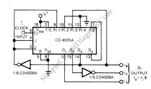
Pulse Generator Produces 3-Phase Output
This is a schematic diagram of a three-phase pulse generator circuit. This circuit produces a three-phase overlapped output similar to a three-phase AC power line.
The three-phase pulse generator circuit is designed to create three-phase output signals that are phase-shifted by...
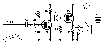
Pulse-Generator & Signal-Tracer
This simple circuit generates narrow pulses at about 700-800Hz frequency. The pulses, containing harmonics up to the MHz region, can be injected into audio or radio-frequency stages of amplifiers, receivers and the like for testing purposes. A high-pitched tone can...
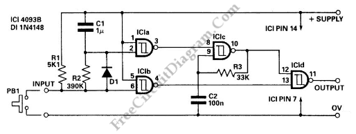
Pulse Delay Generator
This circuit is a delayed pulse generator that provides pulse rate and independent control of the initial delay. The pulse generator of this circuit is.
The delayed pulse generator circuit is designed to produce a pulse output after a specified delay,...
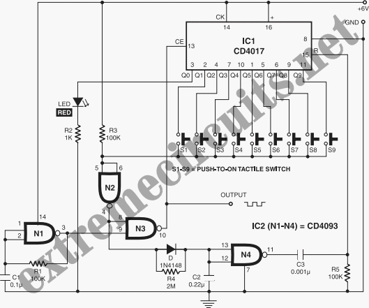
Pulse Generator
This circuit is quite effective for testing or operating counters and stepping relays, as it eliminates the need for manually setting a switch for the desired number of pulses. By pressing the appropriate switches S1 to S9, one can generate...
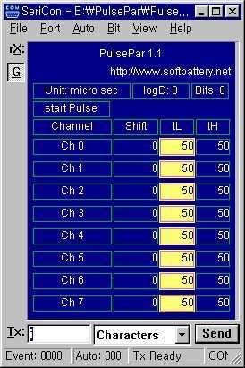
Turn an old PC into a multi-channel pulse generator, for PWM/servo/stepper
PulsePar turns a PC into a multi-channel pulse generator utilizing the parallel port. The period, duty and phase of each channel are adjustable so as to be used in PWM systems as well as in testing servo and stepper (stepping)...
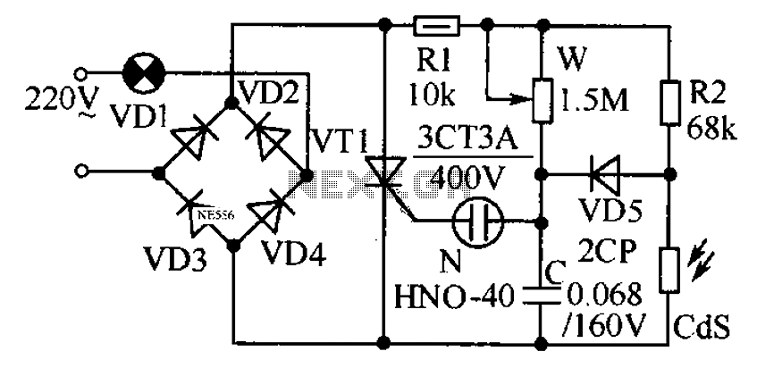
Automatic light regulator circuit diagram
This circuit is designed to automatically adjust the brightness of lights based on the ambient light intensity. In bright conditions, the lights remain off, while in low ambient brightness, the lights are activated. The circuit incorporates a thyristor (VT1) and...
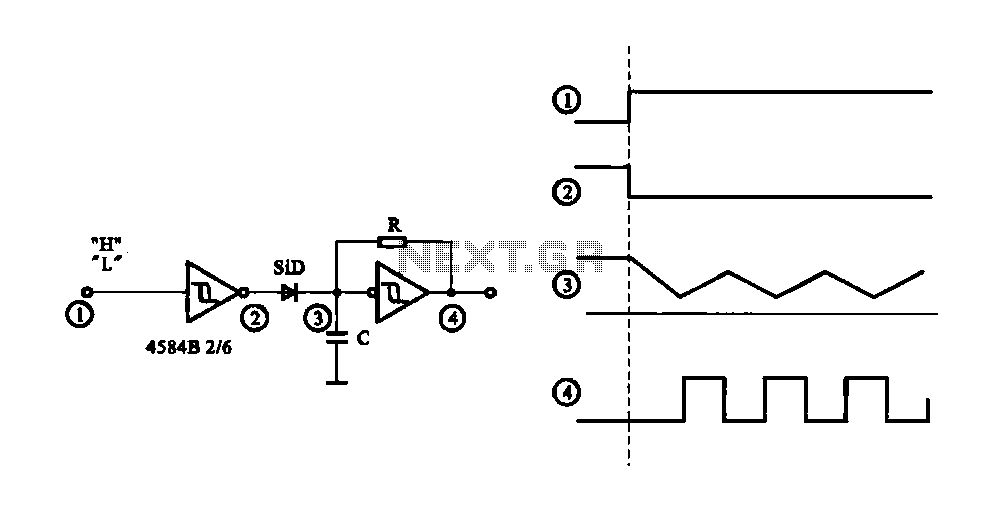
Controlled pulse signal generating circuit
The circuit generates a controlled pulse signal. When a high pulse signal is applied to the input terminal O (start), the output pulse signal is activated. Conversely, when a low signal is received at the input terminal O (stop), the...
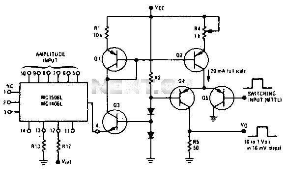
Programmable pulse generator
Fast rise and fall times necessitate the utilization of high-speed switching transistors for the differential pair, Q4 and Q5. Linear ramps and sine waves can be produced using the suitable reference input.
The circuit employs high-speed switching transistors, specifically Q4 and...
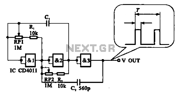
Adjustable pulse generator circuit
An adjustable pulse generator circuit is presented, which produces a periodic signal with independently adjustable pulse widths. The electrical path allows for modifications to the signal period through the adjustment of RP1. Additionally, RP2 can be altered to change the...