


led flasher circuit schematics
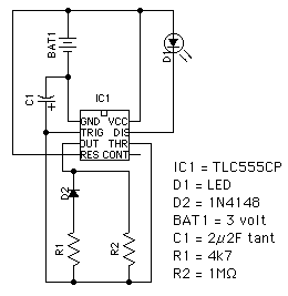
Description: This circuit utilizes the TLC555CP timer integrated circuit to flash an LED approximately twice per second. This specific 555 timer operates on a voltage of only 3 volts, allowing it to be powered by two 1.5-volt cells. When using "AA" cells, the expected battery life can reach up to 6 months. In contrast, with larger "C" or "D" type cells, the circuit can function for several years. The application of this circuit can be integrated into road lane marker bollards or serve as a warning signal for various obstacles such as fences, scaffolding tubes, or parked vehicles. Additionally, it can be suspended from light switch pull cords to enhance visibility in dark environments.
The circuit design employs the TLC555CP timer in astable mode, allowing it to generate a continuous square wave output that drives the LED. The frequency of the flashing can be adjusted by modifying the resistor and capacitor values connected to the timer. Typically, a combination of resistors R1 and R2, along with a timing capacitor C1, will determine the on and off durations of the LED.
To implement this circuit, the power supply is connected to pins 8 (VCC) and 1 (GND) of the TLC555CP. The timing components are connected to pins 6 (threshold) and 2 (trigger), with pin 3 serving as the output pin to drive the LED. A current-limiting resistor should also be included in series with the LED to prevent excessive current flow, which could damage the LED.
For optimal performance, the choice of the timing capacitor is crucial. A larger capacitor will result in a slower flashing rate, while a smaller capacitor will increase the frequency. The circuit can be housed in a weatherproof enclosure if intended for outdoor use, ensuring longevity and reliability.
This versatile flashing LED circuit can be employed in various applications, enhancing visibility and safety in low-light conditions, making it an effective tool for road safety and obstacle marking.This circuit uses the TLC555CP timer I. C. to flash an LED roughly twice every second. This particular type of 555 timer will run off only 3 volts so two 1. 5 volt cells can be used. With "AA" cells, you can expect a battery life of up to 6 months. With larger "C" or "D" type cells it will last for years. The circuit can be incorporated into a roads ide lane marker bollard or used as a warning for other obstacles such as fences, scaffolding tubes or parked vehicles. It can also be suspended from light switch pull-cords to make them easy to find in the dark.
The circuit design employs the TLC555CP timer in astable mode, allowing it to generate a continuous square wave output that drives the LED. The frequency of the flashing can be adjusted by modifying the resistor and capacitor values connected to the timer. Typically, a combination of resistors R1 and R2, along with a timing capacitor C1, will determine the on and off durations of the LED.
To implement this circuit, the power supply is connected to pins 8 (VCC) and 1 (GND) of the TLC555CP. The timing components are connected to pins 6 (threshold) and 2 (trigger), with pin 3 serving as the output pin to drive the LED. A current-limiting resistor should also be included in series with the LED to prevent excessive current flow, which could damage the LED.
For optimal performance, the choice of the timing capacitor is crucial. A larger capacitor will result in a slower flashing rate, while a smaller capacitor will increase the frequency. The circuit can be housed in a weatherproof enclosure if intended for outdoor use, ensuring longevity and reliability.
This versatile flashing LED circuit can be employed in various applications, enhancing visibility and safety in low-light conditions, making it an effective tool for road safety and obstacle marking.This circuit uses the TLC555CP timer I. C. to flash an LED roughly twice every second. This particular type of 555 timer will run off only 3 volts so two 1. 5 volt cells can be used. With "AA" cells, you can expect a battery life of up to 6 months. With larger "C" or "D" type cells it will last for years. The circuit can be incorporated into a roads ide lane marker bollard or used as a warning for other obstacles such as fences, scaffolding tubes or parked vehicles. It can also be suspended from light switch pull-cords to make them easy to find in the dark.
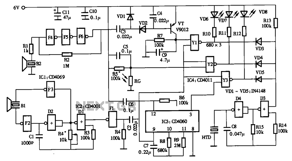
Low power timer switch
The timing circuit utilizes an electronic switch composed of F1, F2, and VT1 to reduce quiescent current to approximately 1 to 2 A with the 555 timer. Upon initial power-up, the voltage across capacitor C2 cannot instantly change, causing the...
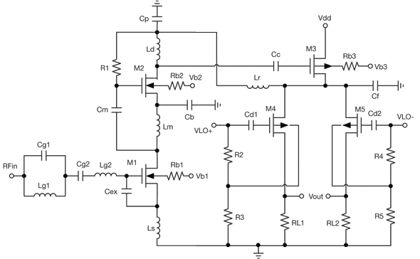
low power receiver serves multiple wireless standards
By combining a current-reuse amplifier and a switch-based mixer, a dual-band receiver front end offers excellent performance with extremely low power consumption.
The dual-band receiver front end integrates a current-reuse amplifier and a switch-based mixer to achieve high performance while maintaining...
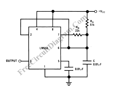
555 IC Oscillator with 50% Duty Cycle
A square wave oscillator utilizing the 555 integrated circuit (IC) can be configured to produce symmetric oscillation with a 50% duty cycle. Additional circuit configurations employ diodes to separate the charging and discharging paths.
The 555 timer IC is a versatile...
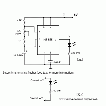
led light flasher
When the preset is set to its maximum, the LED flashes approximately every half second. This flashing rate can be increased by using a larger capacitor value, for instance, changing from 10µF to 22µF will result in a flashing rate...
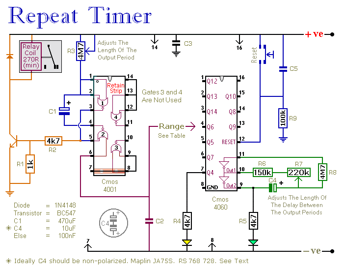
A Timer That Re-Triggers At Regular Intervals
This circuit features an adjustable output timer that can re-trigger at regular intervals. The output duration can range from a fraction of a second to half an hour or more, and it can be configured to recur at intervals from...
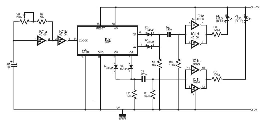
Police Car Lights with LEDs
This circuit simulates the flashing lights of a police car, similar to those seen on British police vehicles. The operational amplifier IC1a functions as a square wave oscillator, with an adjustable frequency controlled by the variable resistor VR1 to achieve...
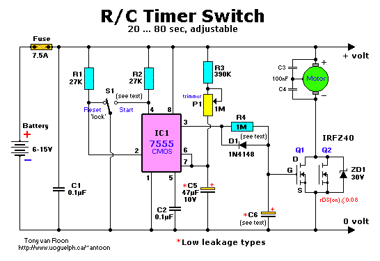
R/C Timer-Switch for Radio Control Applications
The project originated from a request by Tony Bowler, a member of the Long Eaton Club, who sought assistance in converting a "Golden Oldie" model to electric free-flight. He selected Vic Smeed's "Debutante" to be powered by seven AE size...
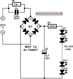
old dick smith catalog mains led circuit
Hello everyone. This is my first post in quite some time. I obviously do not have an old enough catalog for reference. In the data section, there were references to...
The input data indicates a lack of sufficient information regarding the...
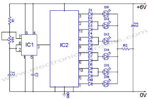
LED Knight RiderCircuit With 4017 and 555 IC
The following circuit illustrates an LED Knight Rider Circuit Diagram. This circuit is based on the 4017 and 555 integrated circuits. Features include the Knight Rider effect with four LEDs.
The LED Knight Rider circuit is designed to create a visual...