


LM139 Measure delay generator Schematic Diagram
#LM139
#delay generator
#sequence generator
#timer circuit
#pulse generator
#time interval
#signal generator
#reset circuit
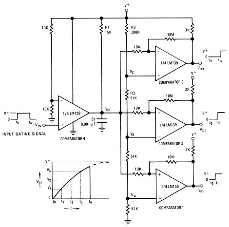
Description: A measure delay generator, also identified similarly to a sequence generator, is a device that provides output signals at specified time intervals from a time reference. It automatically resets when the input signal returns to ground. The schematic illustrates the design of a measure delay generator circuit diagram using the LM139. The LM139 is a precision comparator that enables sensing close to ground, eliminating the need for dual power supplies and minimizing power consumption, making it suitable for battery-operated setups.
The measure delay generator circuit utilizing the LM139 comparator is designed to provide precise timing control for various applications. The circuit operates by comparing an input voltage to a reference voltage, which is set using a resistor divider network. When the input signal exceeds the reference voltage, the LM139 outputs a high signal, initiating a timing interval. The duration of this interval is determined by external timing components, typically a resistor-capacitor (RC) network, which sets the charge and discharge time constants.
Upon reaching the specified delay, the output signal transitions to a low state. The circuit is designed to reset automatically when the input signal returns to ground, ensuring that the timing cycle can repeat without manual intervention. This feature is particularly useful in applications requiring periodic signal generation or synchronization with other circuit components.
The LM139's ability to operate with low voltage levels allows for integration into low-power applications, making it ideal for battery-powered devices. Additionally, the precision of the LM139 ensures that the timing intervals remain consistent, which is critical for applications in timing circuits, pulse generation, and event counting.
Overall, the measure delay generator circuit using the LM139 provides a reliable and efficient solution for generating time-based output signals, suitable for a wide range of electronic applications.Measure delay generator (in addition identified in the same way as sequence generator), is a device which long for provide output signals on prescribed time intervals from a time reference to and will unconsciously reset while the input hint returns to ground. under schematic illustrates the design of a measure Delay Generator Circuit Diagram usin g LM139. The LM139 skin tone from head to foot precision comparators; allows sensing come close to GND; eliminates need in lieu of dual food and power drain apt for battery setup. You are reading the Circuits of LM139 Measure delay generator And this circuit permalink url it is
The measure delay generator circuit utilizing the LM139 comparator is designed to provide precise timing control for various applications. The circuit operates by comparing an input voltage to a reference voltage, which is set using a resistor divider network. When the input signal exceeds the reference voltage, the LM139 outputs a high signal, initiating a timing interval. The duration of this interval is determined by external timing components, typically a resistor-capacitor (RC) network, which sets the charge and discharge time constants.
Upon reaching the specified delay, the output signal transitions to a low state. The circuit is designed to reset automatically when the input signal returns to ground, ensuring that the timing cycle can repeat without manual intervention. This feature is particularly useful in applications requiring periodic signal generation or synchronization with other circuit components.
The LM139's ability to operate with low voltage levels allows for integration into low-power applications, making it ideal for battery-powered devices. Additionally, the precision of the LM139 ensures that the timing intervals remain consistent, which is critical for applications in timing circuits, pulse generation, and event counting.
Overall, the measure delay generator circuit using the LM139 provides a reliable and efficient solution for generating time-based output signals, suitable for a wide range of electronic applications.Measure delay generator (in addition identified in the same way as sequence generator), is a device which long for provide output signals on prescribed time intervals from a time reference to and will unconsciously reset while the input hint returns to ground. under schematic illustrates the design of a measure Delay Generator Circuit Diagram usin g LM139. The LM139 skin tone from head to foot precision comparators; allows sensing come close to GND; eliminates need in lieu of dual food and power drain apt for battery setup. You are reading the Circuits of LM139 Measure delay generator And this circuit permalink url it is
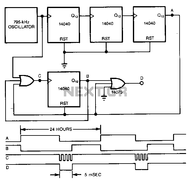
Very-low-duty-cycle-pulse-generator
A precise pulse generator can be constructed using a precision oscillator and several CMOS counters. The number of counters can be increased to extend the pulse period as needed. This circuit will generate a pulse approximately 5 ms long every...
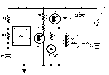
Muscular Bio-Stimulator
IC1 generates 150 µSec pulses at approximately 80Hz frequency. Q1 functions as a buffer, while Q2 inverts the pulse polarity and drives the transformer. The output pulse amplitude is adjusted by P1 and is visually indicated by the brightness of...
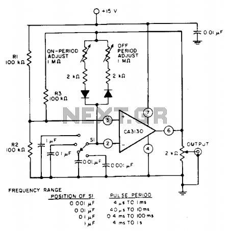
Pulse generator as astable multivibrator
The pulse repetition rate is determined by adjusting switch SI to the desired position, and this rate remains relatively constant even when the resistors that control the on-period and off-period are modified. Resistors R1 and R2 set the biasing of...
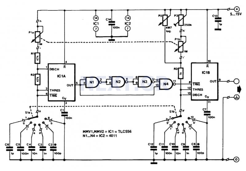
Low Cost Pulse Generator circuit
This pulse generator produces square pulses ranging from 1Hz to 100KHz with an adjustable pulse width of nearly 0-100%. It operates on a voltage of 5-15V, making it suitable for both TTL and CMOS circuits. This device is essential for...
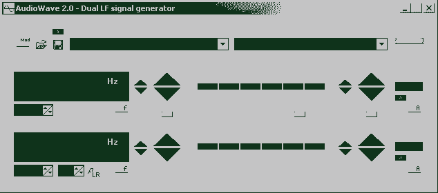
AudioWave 2.0
With AudioWave 2.0 your soundcard becomes a comfortable LF-signal-generator, which produces signals from 1Hz to 20 kHz with a resolution of 1 Hz. Phase shift between left and right channel is adjustable from 180° to +180° and an attenuator can...
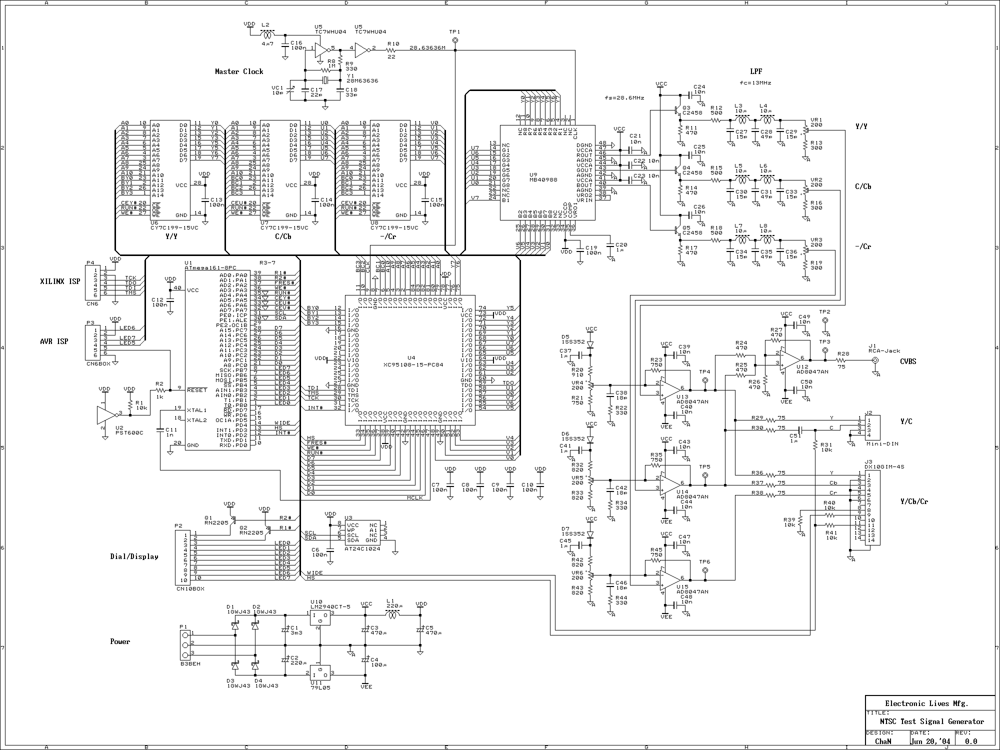
Test Signal Generator
This signal generator uses a three channel DAC to generate Composite video signal (CVBS) and S video signal (Y/C separated) at the same time, left one channel is not used in NTSC format. It is assigned for one of the...
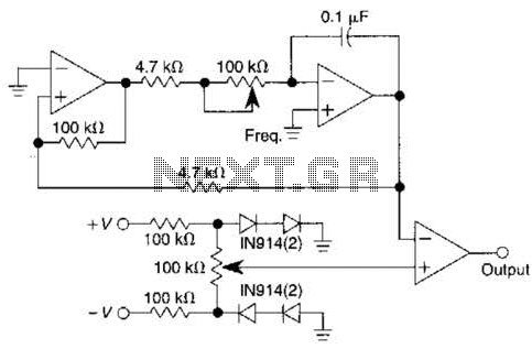
Pulse Generator With Variable Duty Cycle Circuit
This pulse generator utilizes a single integrated circuit (IC) and six passive components to achieve a frequency range of 400 to 4000 Hz, with an adjustable duty cycle ranging from 1% to 99%. The circuit employs a threshold detector (ICA)...
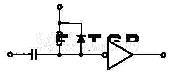
Single pulse signal generating circuit
A single pulse signal generating circuit is depicted, which utilizes switch contacts to create a digital signal for reset or stop functions. This one-shot pulse generating circuit operates as a non-synchronous differential circuit.
The single pulse signal generating circuit, commonly referred...
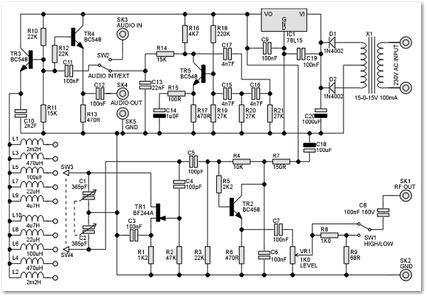
RF Signal Generator circuit
This signal generator is designed for the realignment of radio receivers. The unit is inexpensive and relatively simple but adequately serves its intended purpose. However, the output is not a pure sine wave, which may make it unsuitable for more...