


Micropower monostable circuit diagram
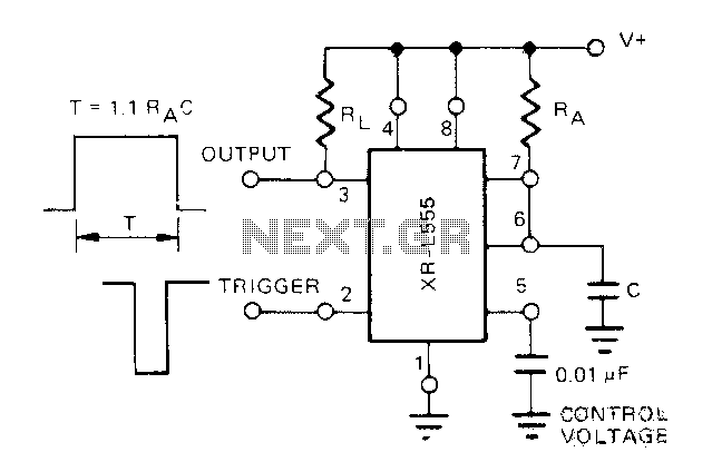
Description: The Exars XR-L555 circuit has a typical power consumption of 900 W and operates with a power supply voltage of 5V. It is a micro-power circuit that can be used as a direct replacement for the standard 555 timer. The delay is controlled by an external resistor (RA) and capacitor (C), which determine the duration of the output pulse.
The Exars XR-L555 is a versatile timer circuit designed for low-power applications. With a power consumption of 900 W, it is optimized for efficiency, making it suitable for battery-operated devices. The circuit operates at a supply voltage of 5V, allowing it to be integrated into various electronic systems that require a reliable timing mechanism.
The XR-L555 functions similarly to the classic 555 timer, providing the same timing capabilities with enhanced performance characteristics. The timing interval is adjustable through the selection of an external resistor (RA) and capacitor (C). The relationship between these components is defined by the formula:
\[ T = 1.1 \times RA \times C \]
where \( T \) is the output pulse duration. By varying the values of RA and C, users can precisely control the timing behavior of the circuit, making it suitable for applications such as pulse width modulation, timer delays, and oscillators.
In addition to its basic timing functions, the XR-L555 may also include features such as a low-power sleep mode, which further enhances its efficiency in power-sensitive applications. The micro-power design ensures that the circuit consumes minimal energy during operation, making it an ideal choice for portable and battery-operated devices.
Overall, the Exars XR-L555 circuit combines the familiar functionality of the traditional 555 timer with modern enhancements that cater to low-power requirements, providing a reliable and flexible solution for a wide range of electronic timing applications.Exars XR-L555 circuit typical power consumption is 900 W, the power supply voltage of 5V, micro-power circuit, XR-L555 can be used directly in place of the 555 timer. Delay by an external resistor and a capacitor (RA and C) control, delay determines the duration of the output pulse.
The Exars XR-L555 is a versatile timer circuit designed for low-power applications. With a power consumption of 900 W, it is optimized for efficiency, making it suitable for battery-operated devices. The circuit operates at a supply voltage of 5V, allowing it to be integrated into various electronic systems that require a reliable timing mechanism.
The XR-L555 functions similarly to the classic 555 timer, providing the same timing capabilities with enhanced performance characteristics. The timing interval is adjustable through the selection of an external resistor (RA) and capacitor (C). The relationship between these components is defined by the formula:
\[ T = 1.1 \times RA \times C \]
where \( T \) is the output pulse duration. By varying the values of RA and C, users can precisely control the timing behavior of the circuit, making it suitable for applications such as pulse width modulation, timer delays, and oscillators.
In addition to its basic timing functions, the XR-L555 may also include features such as a low-power sleep mode, which further enhances its efficiency in power-sensitive applications. The micro-power design ensures that the circuit consumes minimal energy during operation, making it an ideal choice for portable and battery-operated devices.
Overall, the Exars XR-L555 circuit combines the familiar functionality of the traditional 555 timer with modern enhancements that cater to low-power requirements, providing a reliable and flexible solution for a wide range of electronic timing applications.Exars XR-L555 circuit typical power consumption is 900 W, the power supply voltage of 5V, micro-power circuit, XR-L555 can be used directly in place of the 555 timer. Delay by an external resistor and a capacitor (RA and C) control, delay determines the duration of the output pulse.
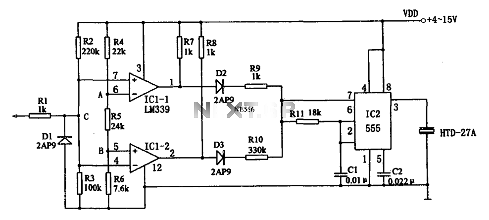
555 sound logic level probe
The acoustic logic level probe circuit consists of a voltage comparator, multivibrator, piezoelectric ceramics (HTD), and other components. The configuration of the audio circuit determines the frequency of the sound level to assess the logic levels of TTL or CMOS...
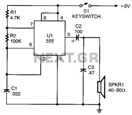
Morse Practice Oscillator Circuit
A 555 timer configured as an astable multivibrator is used in this circuit to generate an audio note. The capacitance value can be changed to vary the audio note as desired.
The circuit utilizes a 555 timer IC, which is...
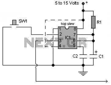
Basic Monostable Multivibrator based IC timer 555
A multivibrator is an electronic circuit used to implement a variety of simple two-state systems such as light-emitting diodes, timers, and flip-flops. The monostable multivibrator will create a condition in which one of the states is stable.
A multivibrator circuit is...
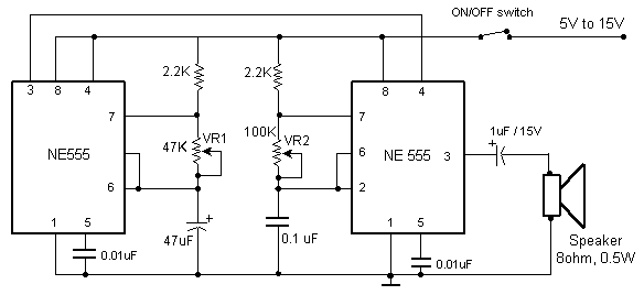
Beeper driver with 555
This circuit produces the sound of a beeper like the one in pagers which produces a "beep-beep" sound. Basically the circuit consists of a 555 timer oscillator which is turned ON and OFF periodically. The first IC (left) oscillates at...
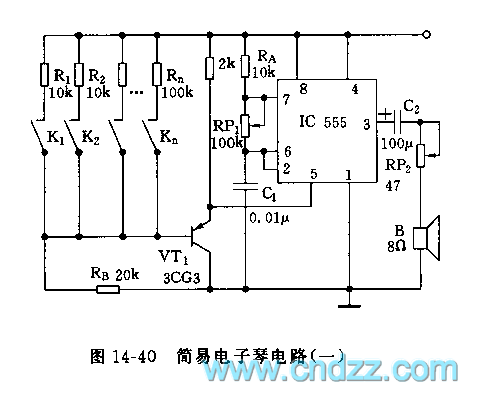
555 simple electronic keyboard circuit
The controllable multivibrator, as illustrated in figure 14-40, consists of a 555 timer along with resistors RA, RP1, and capacitor C1. The oscillation frequency is influenced by the control voltage applied to pin 5. This control voltage is determined by...
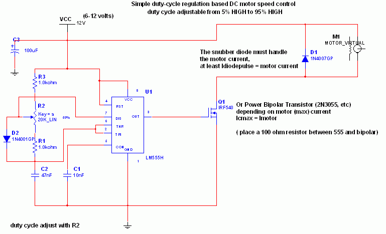
Simple DC motor PWN speed controls
The 555 IC is configured in an astable mode, producing a frequency that remains constant and is independent of the duty cycle. The total resistance (Rcharge + Rdischarge, considering the diode) is fixed at 22 kΩ, yielding a frequency of...
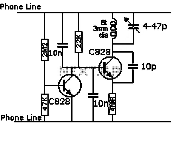
touch switch circuit using 555 ic
This circuit is a touch switch circuit, similar to a touch door alarm. It utilizes a 555 timer as the core component of the touch switch circuit. The operation begins when the plate is touched, triggering the 555 timer. The...
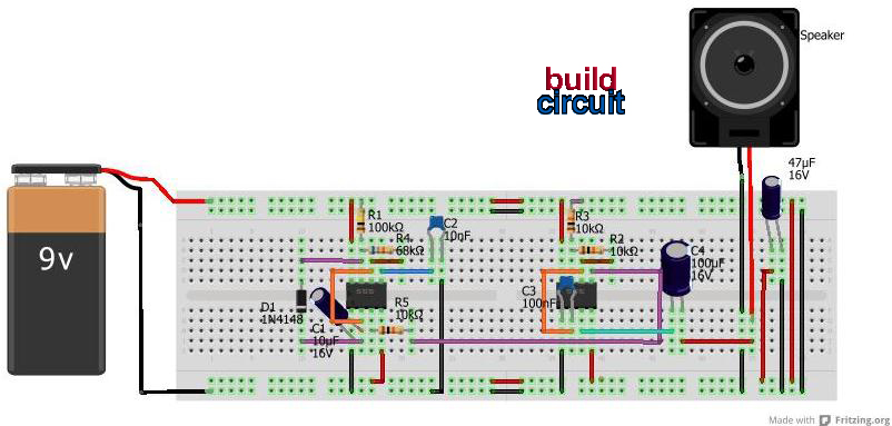
light activated police siren using 555 timer
This project involves a simple light-activated police siren utilizing a light-dependent resistor (LDR) and an NE555 timer. It is advisable to complete some preliminary projects before attempting this one. The NE555 timer, configured in slow astable mode with a resistor...
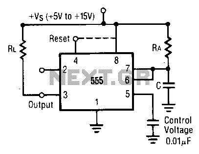
Monostable-operation
In this mode, the timer operates as a one-shot device. The external capacitor is initially kept discharged by a transistor internal to the timer. When a negative trigger pulse is applied to pin 2, the flip-flop is set, causing the...