


One second Audible Clock Circuit Schematic
#clock
#timer
#pulse generator
#audible signal
#time-delay
#metronome
#one-second pulse
#mains supply
#beep
#flash
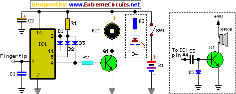
Description: This precise one-pulse-per-second clock is constructed using a few common components and is driven by a 50 or 60 Hertz mains supply, without any direct connection to it. It produces a beep or metronome-like click and/or a visible flash to indicate one-second intervals, making it useful for various applications that require time-delay counting in seconds. The circuit utilizes a CMOS 4024 counter/divider chip and three diodes, configured to divide the frequency of the input signal at pin #1 by 50 or 60, depending on the mains frequency. The input impedance at pin #1 is very high, so merely touching the pin or connecting a short track or piece of wire to it typically suffices to provide the necessary input signal. An alternative method to generate an input signal involves wrapping a piece of wire several times around any convenient mains cable or transformer. No additional connections are required.
This one-pulse-per-second clock circuit is designed to provide a reliable timing signal suitable for various applications, such as timers, metronomes, or other devices requiring precise second intervals. The heart of the circuit is the CMOS 4024 counter/divider chip, which is capable of dividing the input frequency efficiently. The arrangement of the three diodes plays a crucial role in shaping the input signal and ensuring that the division process occurs correctly.
When powered, the circuit captures the 50 or 60 Hertz signal from the mains supply through the high-impedance input at pin #1. This allows the circuit to function without being directly connected to the mains, enhancing safety and reducing the risk of electrical interference. The high input impedance means that the circuit is sensitive enough to detect even minimal changes in voltage, which is ideal for applications where precision timing is essential.
The output of the CMOS 4024 chip generates a clean one-second pulse that can be used to trigger other devices or circuits. The beep or metronome-like click provides an audible indication of each pulse, while the visual flash serves as a secondary confirmation, making it suitable for environments where audible signals may not be easily perceived.
In summary, this one-pulse-per-second clock circuit is a versatile and efficient solution for generating accurate timing signals using common electronic components, making it accessible for hobbyists and professionals alike. The design's simplicity and effectiveness in producing a reliable one-second pulse make it an excellent choice for a wide range of timing applications.This accurate one-pulse-per-second clock is made with a few common parts and driven from a 50 or 60 Hertz mains supply but with no direct connection to it. A beep or metronome-like click and/or a visible flash, will beat the one-second time and can be useful in many applications in which some sort of time-delay counting in seconds is desirable.
Th e circuit is formed by a CMos 4024 counter/divider chip and 3 diodes, arranged to divide the frequency of the input signal at pin #1 by 50 (or 60, see Notes). The input impedance at pin #1 is very hight, so simply touching the pin (or a short track or piece of wire connected to it) is usually enough to provide the necessary input signal.
Another way to provide an input signal consists in a piece of wire wrapped several times around any convenient mains cable or transformer. No other connection is necessary. This accurate one-pulse-per-second clock is made with a few common parts and driven from a 50 or 60 Hertz mains supply but with no direct connection to it.
A beep or metronome-like click and/or a visible flash, will beat the one-second time and can be useful in many applications in which some sort of time-delay counting in seconds is desirable. The circuit is formed by a CMos 4024 counter/divider chip and 3 diodes, arranged to divide the frequency of the input signal at pin #1 by 50 (or 60, see Notes).
This one-pulse-per-second clock circuit is designed to provide a reliable timing signal suitable for various applications, such as timers, metronomes, or other devices requiring precise second intervals. The heart of the circuit is the CMOS 4024 counter/divider chip, which is capable of dividing the input frequency efficiently. The arrangement of the three diodes plays a crucial role in shaping the input signal and ensuring that the division process occurs correctly.
When powered, the circuit captures the 50 or 60 Hertz signal from the mains supply through the high-impedance input at pin #1. This allows the circuit to function without being directly connected to the mains, enhancing safety and reducing the risk of electrical interference. The high input impedance means that the circuit is sensitive enough to detect even minimal changes in voltage, which is ideal for applications where precision timing is essential.
The output of the CMOS 4024 chip generates a clean one-second pulse that can be used to trigger other devices or circuits. The beep or metronome-like click provides an audible indication of each pulse, while the visual flash serves as a secondary confirmation, making it suitable for environments where audible signals may not be easily perceived.
In summary, this one-pulse-per-second clock circuit is a versatile and efficient solution for generating accurate timing signals using common electronic components, making it accessible for hobbyists and professionals alike. The design's simplicity and effectiveness in producing a reliable one-second pulse make it an excellent choice for a wide range of timing applications.This accurate one-pulse-per-second clock is made with a few common parts and driven from a 50 or 60 Hertz mains supply but with no direct connection to it. A beep or metronome-like click and/or a visible flash, will beat the one-second time and can be useful in many applications in which some sort of time-delay counting in seconds is desirable.
Th e circuit is formed by a CMos 4024 counter/divider chip and 3 diodes, arranged to divide the frequency of the input signal at pin #1 by 50 (or 60, see Notes). The input impedance at pin #1 is very hight, so simply touching the pin (or a short track or piece of wire connected to it) is usually enough to provide the necessary input signal.
Another way to provide an input signal consists in a piece of wire wrapped several times around any convenient mains cable or transformer. No other connection is necessary. This accurate one-pulse-per-second clock is made with a few common parts and driven from a 50 or 60 Hertz mains supply but with no direct connection to it.
A beep or metronome-like click and/or a visible flash, will beat the one-second time and can be useful in many applications in which some sort of time-delay counting in seconds is desirable. The circuit is formed by a CMos 4024 counter/divider chip and 3 diodes, arranged to divide the frequency of the input signal at pin #1 by 50 (or 60, see Notes).
Clocks
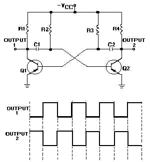
Clocks have been discussed previously in relation to their interaction with flip-flops (FFs). It is important to note that a clock generates a timing signal used to control operations. This control mechanism is evident in both D and J-K flip-flops....
Timer circuit
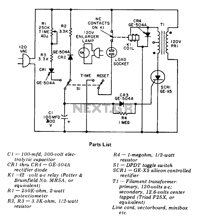
This precision solid-state time delay circuit features both delayed off and delayed on switch functions, which can be interchanged by simply swapping the relay contacts.
The described time delay circuit is designed to provide precise control over the timing of switching...
Kodak Flash circuit
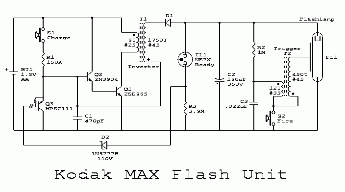
This flash circuit is a typical camera flash.
This flash circuit functions as a high-voltage power supply for camera flash units, enabling the rapid discharge of energy to produce a bright flash of light. The primary components of a typical camera...

metronome circuit
The figure illustrates a simple project schematic of a metronome. A metronome is a device utilized by musicians to produce continuous beats through a speaker.
The metronome circuit typically consists of several key components that work together to generate a stable...
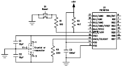
Clock Oscillator BasicCircuit from Sirius microSystem
The following file contains detailed information about the design of a basic clock oscillator circuit diagram. Included in this file is information about selecting the components.
The clock oscillator circuit is a fundamental component in various electronic systems, providing a stable...
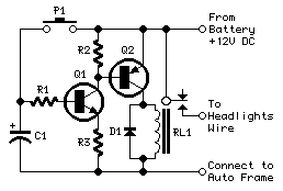
Headlights Timer
This device is a simple timer, allowing to keep on the headlights of your vehicle for about 1min. and 30sec., e.g. when accessing some dark place, without the necessity of coming back to switch-off the lights.
The circuit design for this...
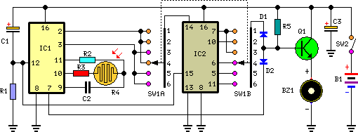
tan timer schematics
This timer is intended for individuals seeking to achieve a tan while minimizing excessive exposure to sunlight. A rotary switch adjusts the timer based on six categorized photo-types. A photoresistor modifies the preset time value in relation to sunlight brightness....
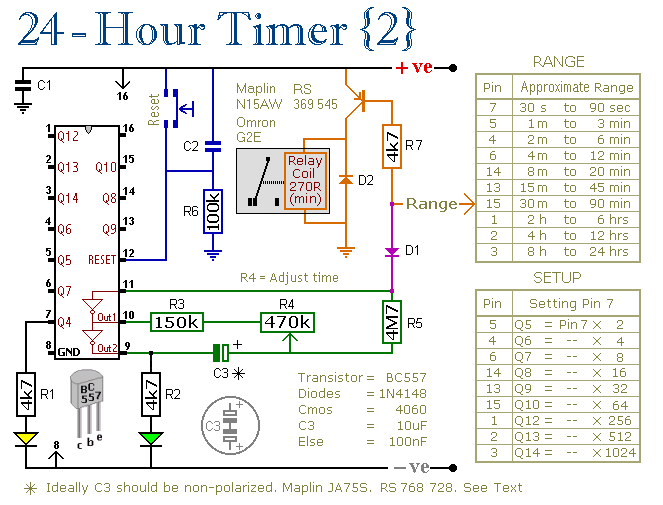
Two Simple 24-Hour Timer Circuit Schematics
These two circuits are multi-range timers that offer periods of up to 24 hours and beyond. They can function as repeating timers or single-shot timers. Both circuits are fundamentally the same, with the primary distinction being their behavior in single-shot...
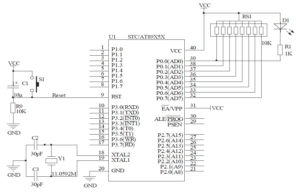
Timing within the one-chip computer Counter and interrupt system
This document will present an overview of two critical components within a one-chip computer: the timing/counter system and the interrupt system. Through this explanation, readers will gain insight into the operating principles of these systems. For illustration, consider an alarm...