


Pulse-width modulator
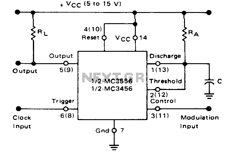
Description: If the timer is activated by a continuous pulse train in the monostable mode, the capacitor's charge time can be adjusted by altering the control voltage at pin 3. In this way, the output pulse width can be modulated by applying a modulating signal that influences the threshold voltage.
In a monostable timer circuit, such as those utilizing the 555 timer IC, the operation relies on a single stable state and a temporary unstable state. When triggered by a pulse, the timer generates a single output pulse of a defined duration. The width of this output pulse is primarily determined by the time constant formed by the resistor-capacitor (RC) network connected to the timing capacitor.
In this configuration, pin 3 serves as the control voltage input, allowing for dynamic adjustment of the threshold voltage that dictates when the timer resets. By varying the voltage at pin 3, the effective threshold voltage can be modified, thus altering the charge time of the capacitor. This adjustment leads to a change in the output pulse width, enabling applications such as pulse width modulation (PWM) where precise control over the pulse duration is required.
The ability to apply a modulating signal to pin 3 introduces an additional layer of flexibility. This signal can be derived from various sources, such as a potentiometer, another waveform generator, or a digital control signal, allowing for real-time modulation of the output pulse width. This feature is particularly useful in applications where the timing characteristics need to adapt to varying conditions, such as in motor speed control, light dimming, or audio signal processing.
The overall functionality of the monostable timer in this context emphasizes the importance of the RC network and control voltage manipulation, showcasing its versatility in electronic design for a range of applications requiring precise timing control.if the timer is triggered with a continuous pulse train in the monostable mode of operation, the charge time of the capacitor can be varied by changing the control voltage at pin 3 In this manner, the output pulse width can be modulated by applying a modulating signal that controls the threshold voltage.
In a monostable timer circuit, such as those utilizing the 555 timer IC, the operation relies on a single stable state and a temporary unstable state. When triggered by a pulse, the timer generates a single output pulse of a defined duration. The width of this output pulse is primarily determined by the time constant formed by the resistor-capacitor (RC) network connected to the timing capacitor.
In this configuration, pin 3 serves as the control voltage input, allowing for dynamic adjustment of the threshold voltage that dictates when the timer resets. By varying the voltage at pin 3, the effective threshold voltage can be modified, thus altering the charge time of the capacitor. This adjustment leads to a change in the output pulse width, enabling applications such as pulse width modulation (PWM) where precise control over the pulse duration is required.
The ability to apply a modulating signal to pin 3 introduces an additional layer of flexibility. This signal can be derived from various sources, such as a potentiometer, another waveform generator, or a digital control signal, allowing for real-time modulation of the output pulse width. This feature is particularly useful in applications where the timing characteristics need to adapt to varying conditions, such as in motor speed control, light dimming, or audio signal processing.
The overall functionality of the monostable timer in this context emphasizes the importance of the RC network and control voltage manipulation, showcasing its versatility in electronic design for a range of applications requiring precise timing control.if the timer is triggered with a continuous pulse train in the monostable mode of operation, the charge time of the capacitor can be varied by changing the control voltage at pin 3 In this manner, the output pulse width can be modulated by applying a modulating signal that controls the threshold voltage.
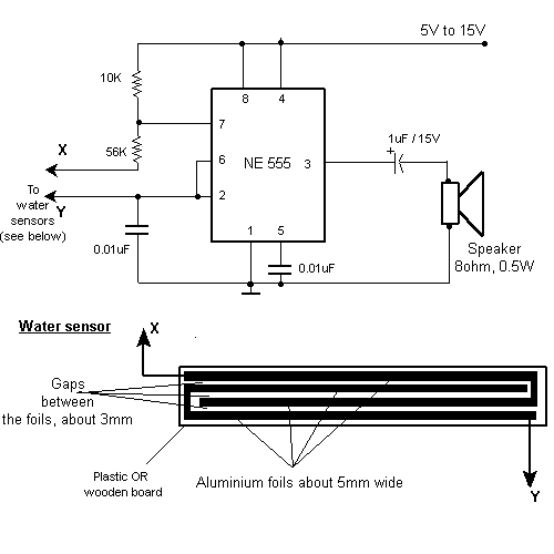
TV remote control blocker/jammer circuit diagram
This small device can be aimed at a television to jam the remote control signal. The circuit design is straightforward. A 555 timer is configured as an astable multivibrator operating at a frequency of approximately 38 kHz, which is the...
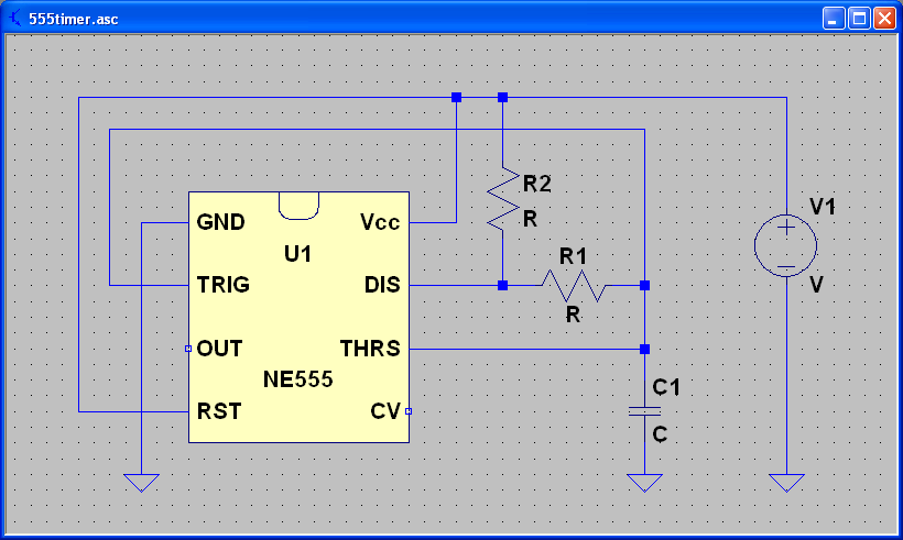
Capacitors and the 555 Timer
ECEN 2250 myDAQ Experiment Capacitors and the 555 Timer.
The experiment involving capacitors and the 555 timer within the ECEN 2250 myDAQ framework focuses on understanding the behavior of capacitors in electronic circuits and the functionality of the 555 timer as...
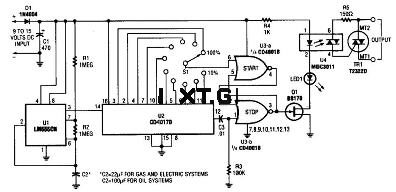
Furnace Fuel Miser Circuit
A timer (LM555CN) and decode counter are utilized to generate duty cycles ranging from 10% to 100% for controlling the operational time of a heating system. V2 operates as a decode counter that can be adjusted for duty cycles between...
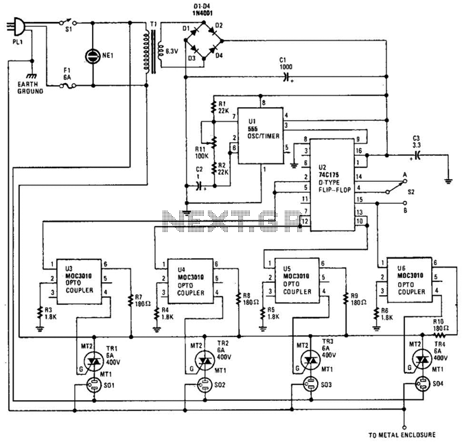
Holiday Light Sequencer Circuit
The integrated circuit U1 (a 555 oscillator/timer) is configured as a conventional pulse generator. The frequency of the pulse generator is adjusted using potentiometer R11. Resistor R2 limits the maximum frequency attainable. The output from the pulse generator is connected...
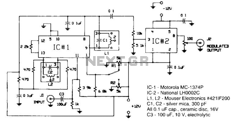
555 Fm Circuit Circuit
Circuit for applying a DC-coupled FM or PPM to a 555 configured as an oscillator. IC-1 is a Motorola MC-1374P, and IC-2 is a National LH0002C. L1 and L2 are Mouser Electronics #421IF200. C1 and C2 are silver mica capacitors...
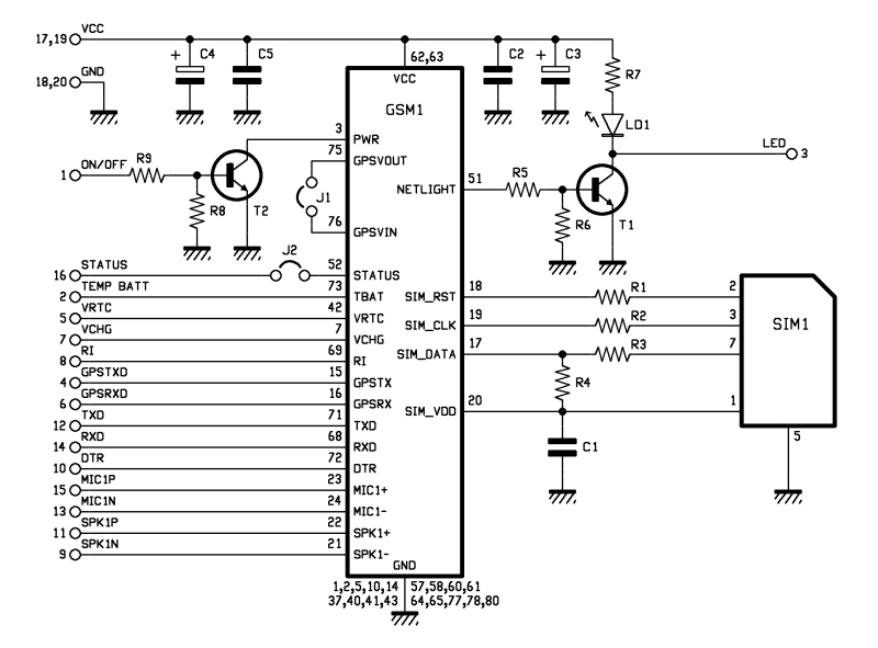
Help me Understand this Circuit Schematic
The roles of capacitors C1, C4, and C5 in a circuit may not be immediately clear. Capacitors on the power rail help to smooth out the signal by reducing current ripple, which can be observed using an oscilloscope. Resistors R6...
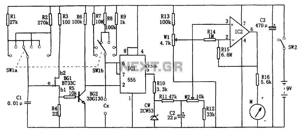
555 the DC capacitor tester
The circuit illustrated in Figure 555 represents a DC capacitor tester. This tester includes a pulse generator, a single-shot circuit, and a head indicating DC amplifier circuit. It is capable of measuring capacitance in the range of nanofarads (nF) and...
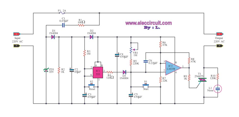
timer control 1 15 minutes by triac 2n6075 and lm555 lm358
Most timer circuits are often used with electrical transformers operating at low voltages such as 9V and 12V, and they incorporate electrical control relays. The timer can be set for durations ranging from 1 to 15 minutes.
Timer circuits are essential...
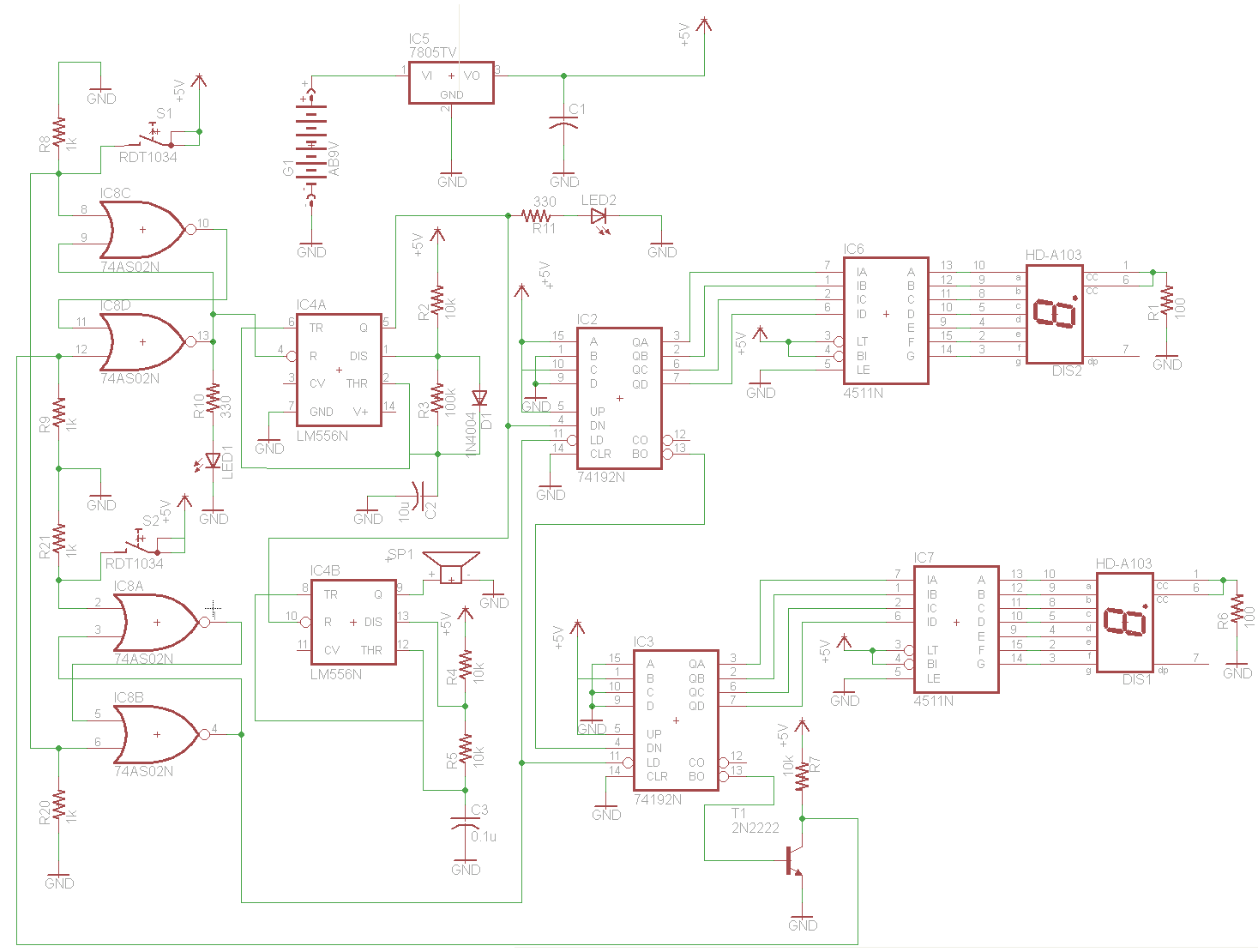
Beeping Down Counter Circuit
The schematic for this project is visually acceptable, although it is not the most refined layout for a schematic. The basic flow progresses from left to right, starting with the state machine, followed by the 555 timers, then the counter...