


Timer LM555 Circuits
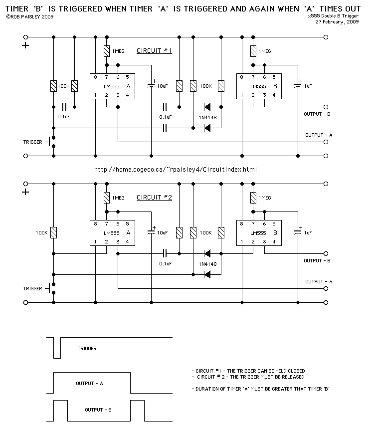
Description: The following are LM555 timer circuits that have unusual functions. Designed to time a sports event; In this circuit the GREEN output is adjusted to be on for 3 minutes and then the RED output is set for 1 minute in a repeating cycle. Each time the light changes a buzzer will sound for about 2 seconds. More: The timing cycle can be stopped and reset/started with the push buttons shown on the schematic.
The described circuit utilizes an LM555 timer IC configured in astable mode to generate a timing sequence suitable for sports events. The primary function of this circuit is to alternate between two outputs: a GREEN LED that remains illuminated for a duration of 3 minutes and a RED LED that lights up for 1 minute, creating a clear visual indication of the timing cycle.
The timing intervals are determined by the resistors and capacitors connected to the LM555 timer. The first timing period for the GREEN output can be achieved by selecting appropriate resistor values (R1 and R2) and a capacitor (C1) to set the duration to 180 seconds (3 minutes). The RED output timing is similarly configured, requiring a different set of resistor and capacitor values to achieve a 60-second (1 minute) duration.
A buzzer is integrated into the circuit to provide an audible signal at each transition between the GREEN and RED states. This buzzer is activated through the output pin of the LM555, programmed to sound for approximately 2 seconds each time the output changes state.
To enhance user interaction, the circuit includes push buttons that allow the user to stop, reset, and start the timing cycle. These buttons are connected to the reset pin of the LM555 timer, enabling the user to control the timing sequence easily. When the reset button is pressed, the timing cycle is halted, and the outputs revert to their initial state, ready for a new timing session.
Overall, this LM555 timer circuit provides a simple yet effective solution for timing sports events, combining visual and audible signals to enhance user experience. Proper selection of components and careful layout design will ensure reliable operation throughout the intended use.The following are LM555 timer circuits that have unusual functions. Designed to time a sports event; In this circuit the GREEN output is adjusted to be on for 3 minutes and then the RED output is set for 1 minute in a repeating cycle. Each time the light changes a buzzer will sound for about 2 seconds. The timing cycle can be stopped and reset/started with the push buttons shown on the schematic.
The described circuit utilizes an LM555 timer IC configured in astable mode to generate a timing sequence suitable for sports events. The primary function of this circuit is to alternate between two outputs: a GREEN LED that remains illuminated for a duration of 3 minutes and a RED LED that lights up for 1 minute, creating a clear visual indication of the timing cycle.
The timing intervals are determined by the resistors and capacitors connected to the LM555 timer. The first timing period for the GREEN output can be achieved by selecting appropriate resistor values (R1 and R2) and a capacitor (C1) to set the duration to 180 seconds (3 minutes). The RED output timing is similarly configured, requiring a different set of resistor and capacitor values to achieve a 60-second (1 minute) duration.
A buzzer is integrated into the circuit to provide an audible signal at each transition between the GREEN and RED states. This buzzer is activated through the output pin of the LM555, programmed to sound for approximately 2 seconds each time the output changes state.
To enhance user interaction, the circuit includes push buttons that allow the user to stop, reset, and start the timing cycle. These buttons are connected to the reset pin of the LM555 timer, enabling the user to control the timing sequence easily. When the reset button is pressed, the timing cycle is halted, and the outputs revert to their initial state, ready for a new timing session.
Overall, this LM555 timer circuit provides a simple yet effective solution for timing sports events, combining visual and audible signals to enhance user experience. Proper selection of components and careful layout design will ensure reliable operation throughout the intended use.The following are LM555 timer circuits that have unusual functions. Designed to time a sports event; In this circuit the GREEN output is adjusted to be on for 3 minutes and then the RED output is set for 1 minute in a repeating cycle. Each time the light changes a buzzer will sound for about 2 seconds. The timing cycle can be stopped and reset/started with the push buttons shown on the schematic.
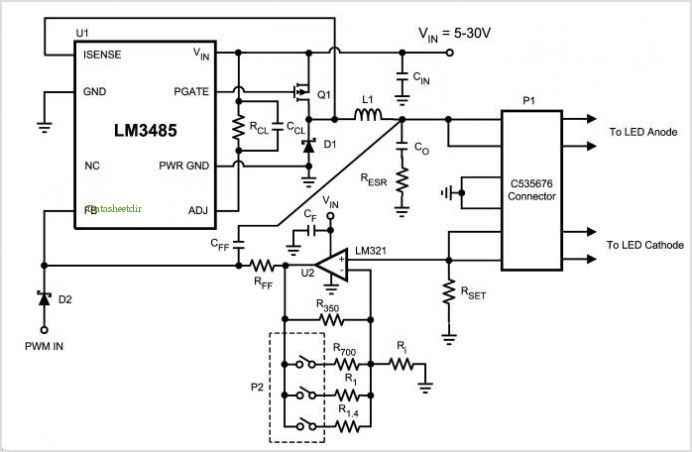
Lm3485 Led Demo Board
The LM4550 is an audio codec designed for PC systems, fully compliant with PC99 standards, and performs the analog-intensive functions of the AC97 Rev2.1 architecture. It utilizes 18-bit Sigma-Delta analog-to-digital (A/D) and digital-to-analog (D/A) converters, providing a dynamic range of...
Knightrider lights for model carss
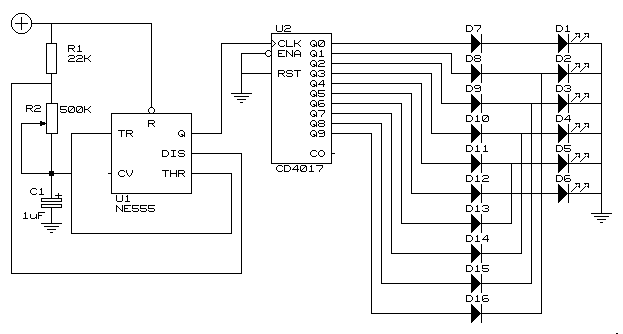
This simple circuit drives six LEDs in a "Knightrider scanner mode." Power consumption primarily depends on the type of LEDs used, particularly when employing a 7555 (555 CMOS version).
The circuit operates by sequentially illuminating the LEDs to create a visual...

Wave Joule Thief circuit
A series of LEDs that turn on and off in a precise sequence, creating a calming and hypnotic effect. Various LED chaser, scanner, and sequencer circuits exist, utilizing discrete transistors, logic integrated circuits (ICs), or microcontrollers. However, a common limitation...
led lights using analog flip flop circuit diagram
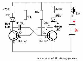
This circuit is designed to drive a total of 42 LEDs, assuming a forward voltage of approximately 2.2V per LED and a forward current of around 21mA for adequate brightness. If the specifications of the LEDs differ significantly, modifications to...
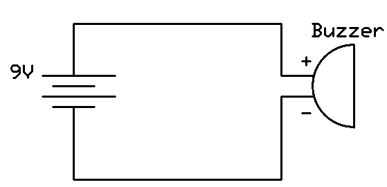
Buzzer Circuit
This project involves connecting the positive terminal of the battery to the positive lead of the buzzer and the negative terminal of the battery to the negative lead of the buzzer. Typically, the positive lead of the buzzer is red,...
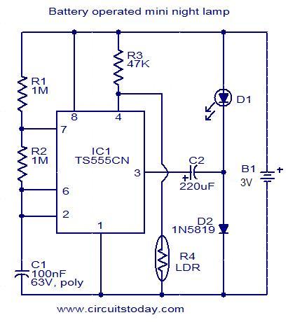
Battery operated mini night lamp
This circuit is designed as a low-power LED night lamp that automatically switches off during daytime. The CMOS timer IC TS555CN is configured as a square wave generator operating at approximately 5 Hz. The output voltage from the IC is...
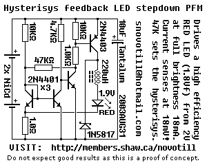
LED stepdown power supply
Below is a proof of concept circuit which needs improvement. The part values shown will run a high efficiency red LED with a Vf of 1.9V from only 2 nicads, right down to 2 volts. For a white LED you...
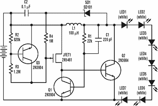
Low power long life LED flashlight Joule Thief circuit
A low power, long-life LED flashlight circuit. Electronic Design proposed a simple circuit to resolve this in a recent article. The front end of their circuit draws less than a milliamp of extra current.
The described LED flashlight circuit is designed...
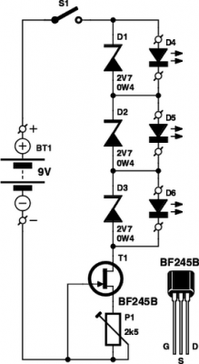
LED Tester
These small electronic lamps are incredibly useful and have a remarkably long lifespan. Approximately 40 years after Nick Holonyak developed the first LED, they have become essential components in various applications. Any dedicated electronics hobbyist typically keeps a selection of...