


Use of one hour LM122 timer circuit
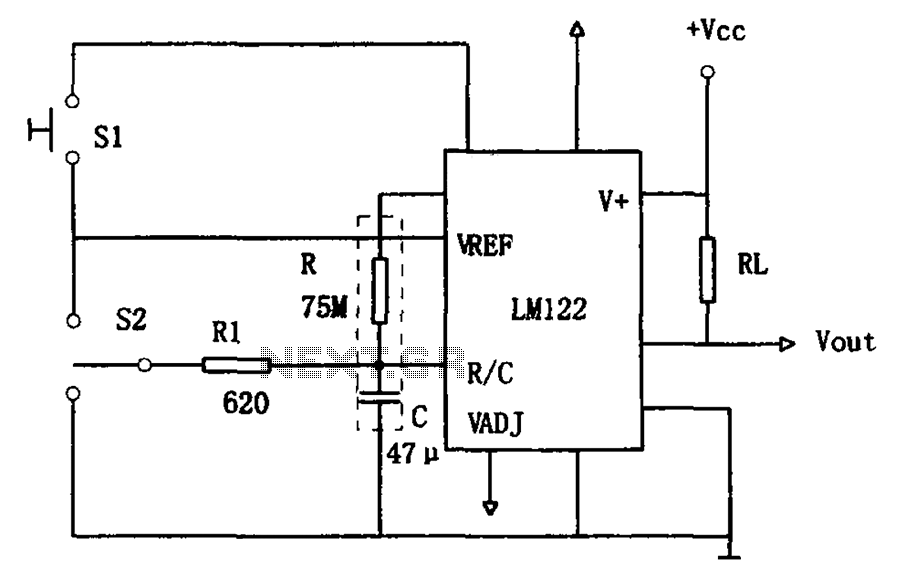
Description: The circuit utilizes an LM122 timer, as illustrated in Figure 1, to manage various timing operations, including starting, resetting, and halting the process midway through. The operation of the circuit is governed by switching mechanisms. Switch S1 initiates the timing process; however, once the timer is activated, the effect of S1 is negated. Switch S2 is positioned centrally in the "off" state, allowing the timer to transition through the phases of charging, opening, and discharging. If the timer is halted midway during the charging phase, even if the preset time has not been reached, the charging mechanism will revert to the operational status of the timer output lines. When the capacitor (C) discharges, the voltage at the R/C terminal drops to zero, placing the discharge position in a standby state, awaiting the start signal from S1. The operational status of the timer output lines remains unchanged even in the recovery position. Consequently, when the timer is reset, the output line maintains its state, and during this period, capacitor C begins to charge again, thus initiating a new timing cycle.
The LM122 timer circuit is designed to perform a variety of timing functions based on the configuration of its components. The circuit typically includes a capacitor (C), a resistor (R), and two switches (S1 and S2). The LM122, a versatile timer IC, operates by charging and discharging the capacitor through the resistor, which determines the timing intervals.
Upon activation by switch S1, the timer begins its cycle. The capacitor charges through the resistor, and the voltage across the capacitor increases until it reaches a predetermined threshold, at which point the timer output toggles. This output can be used to control other devices or components in the circuit.
Switch S2 serves as a control mechanism that can halt the timing process at any point. When S2 is in the off position, the circuit is effectively disabled, preventing any further timing operations. However, once S1 is activated again, the timer resumes its operation from the point it was stopped, allowing for flexible timing control.
The behavior of the circuit during the discharging phase is critical. When the capacitor discharges, the voltage at the R/C terminal drops to zero, indicating that the timer is ready to receive a new start signal. The design ensures that the timer's operational state does not change during the reset process, which is crucial for maintaining the integrity of the timing function.
In summary, the LM122 timer circuit is a robust design that allows for precise timing control through the strategic use of switches and passive components. Its ability to handle interruptions and resume timing operations makes it suitable for a variety of applications where timing accuracy is essential. As shown in Figure 1 hour using a LM122 timer circuit. Start of the circuit, reset and stop halfway, etc. are converted by the switching operation. Figure, S1 to start timing w hen the timer is started, then this switch has no effect. S2 is centrally located in the off switch, the timer can switch through the conversion is completed: Charge - open - discharge. Since midway stop charging, even if not to the timer set time, the charging station will return to work status timer output lines.
When the C discharge, R/C terminal voltage is zero, the discharge position waiting for start signal S1. Even if the recovery position. Work status timer output line does not change, therefore, the timer is reset when the work which the state remains the same output line, in this moment, C starts charging again, start a timer to change working hours.
The LM122 timer circuit is designed to perform a variety of timing functions based on the configuration of its components. The circuit typically includes a capacitor (C), a resistor (R), and two switches (S1 and S2). The LM122, a versatile timer IC, operates by charging and discharging the capacitor through the resistor, which determines the timing intervals.
Upon activation by switch S1, the timer begins its cycle. The capacitor charges through the resistor, and the voltage across the capacitor increases until it reaches a predetermined threshold, at which point the timer output toggles. This output can be used to control other devices or components in the circuit.
Switch S2 serves as a control mechanism that can halt the timing process at any point. When S2 is in the off position, the circuit is effectively disabled, preventing any further timing operations. However, once S1 is activated again, the timer resumes its operation from the point it was stopped, allowing for flexible timing control.
The behavior of the circuit during the discharging phase is critical. When the capacitor discharges, the voltage at the R/C terminal drops to zero, indicating that the timer is ready to receive a new start signal. The design ensures that the timer's operational state does not change during the reset process, which is crucial for maintaining the integrity of the timing function.
In summary, the LM122 timer circuit is a robust design that allows for precise timing control through the strategic use of switches and passive components. Its ability to handle interruptions and resume timing operations makes it suitable for a variety of applications where timing accuracy is essential. As shown in Figure 1 hour using a LM122 timer circuit. Start of the circuit, reset and stop halfway, etc. are converted by the switching operation. Figure, S1 to start timing w hen the timer is started, then this switch has no effect. S2 is centrally located in the off switch, the timer can switch through the conversion is completed: Charge - open - discharge. Since midway stop charging, even if not to the timer set time, the charging station will return to work status timer output lines.
When the C discharge, R/C terminal voltage is zero, the discharge position waiting for start signal S1. Even if the recovery position. Work status timer output line does not change, therefore, the timer is reset when the work which the state remains the same output line, in this moment, C starts charging again, start a timer to change working hours.
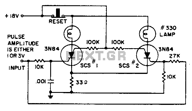
Pulse-amplitude-discriminator
A 1-V amplitude pulse activates SCR1, but lacks sufficient amplitude to activate SCR2. A 3-V input pulse is delayed in reaching SCR1 due to the 10-KΩ and 0.001-µF integrating network. Instead, it activates SCR2, subsequently increasing the common emitter voltage...
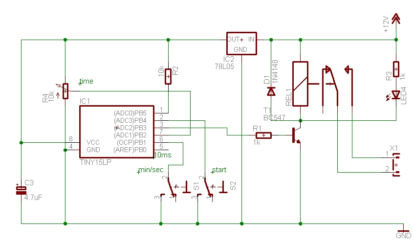
Timer circuit
The time can be set using a potentiometer ranging from 1 minute to 1023 minutes, approximately 17 hours. A pushbutton initiates the timing process, activates a relay, and the timer will deactivate the relay once the set time has elapsed....
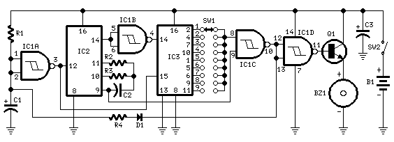
Jogging Timer
This circuit was developed in response to requests from visitors for a timer that can emit a beep after intervals of one, two, three minutes, and so forth, suitable for jogging purposes. As illustrated in the circuit diagram, SW1 is...
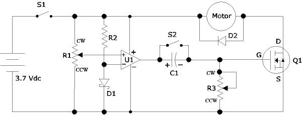
Airplane Flight Timer
The following circuit illustrates an Airplane Flight Timer Circuit Diagram. Features include switches in the closed position and battery voltage maintained at a safe level.
The Airplane Flight Timer Circuit is designed to provide a reliable timing mechanism for monitoring flight...
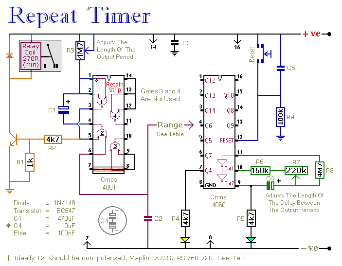
A Regularly Repeating Interval Timer circuit
This circuit features an adjustable output timer capable of re-triggering at regular intervals. The output duration can range from a fraction of a second to over half an hour, and it can be configured to recur at regular intervals from...
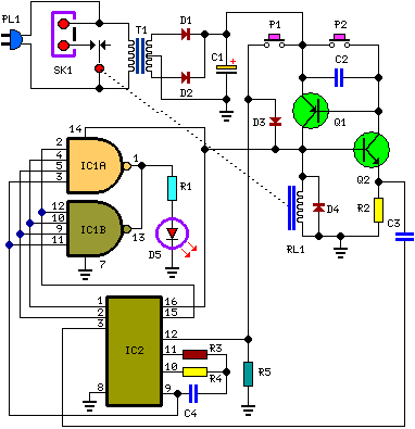
bedside lamp timer schematics
Q1 and Q2 create an ALL-ON ALL-OFF circuit that, when in the off state, draws negligible current. P1 initiates the circuit, activating the relay and powering the two integrated circuits (ICs). The lamp is energized through the relay switch, and...
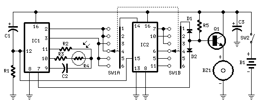
Timer
This timer was designed for people wanting to get tanned but at the same time wishing to avoid an excessive exposure to sunlight. A Rotary Switch sets the timer according to six classified Photo-types. A Photo resistor extends the preset...
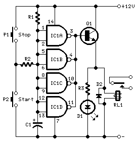
long delay timer circuit diagram
This timer was designed primarily to turn off a portable radio after a specific duration. This feature allows users to fall asleep on the beach or in a hammock, with the assurance that the radio will automatically shut off after...
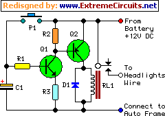
car headlights timer schematics
This device functions as a simple timer that keeps the vehicle's headlights on for approximately 1 minute and 30 seconds, allowing access to dark areas without the need to return and switch off the lights. Pressing switch P1 enables capacitor...