


Voltage-to-Pulse Duration Converter
#voltage-to-pulse
#timer IC
#OP Amp
#pulse duration
#signal conversion
#555 timer
#analog to digital
#waveform generation
#precision timing
#circuit design
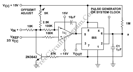
Description: This is a circuit for a Voltage-to-Pulse Duration Converter. The circuit is designed to convert voltage into pulse duration by integrating a timer IC and an operational amplifier (OP Amp).
The Voltage-to-Pulse Duration Converter circuit utilizes a timer IC, typically the 555 timer, configured in monostable mode. In this configuration, the timer generates a pulse of a specified duration in response to a triggering voltage input. The duration of the output pulse is determined by the resistor and capacitor values connected to the timer.
An operational amplifier is employed to condition the input voltage signal. The OP Amp can be configured as a comparator to compare the input voltage against a reference voltage. When the input voltage exceeds the reference level, the OP Amp output triggers the timer IC, initiating the pulse generation.
In designing the circuit, it is essential to select appropriate resistor and capacitor values to achieve the desired pulse duration. The relationship between the pulse width (T) and the RC network can be described by the formula T = 1.1 * R * C, where R is the resistance in ohms and C is the capacitance in farads.
The operational amplifier's gain settings may also need adjustment to ensure proper triggering of the timer IC. Additionally, power supply considerations are critical, as both the OP Amp and timer IC require stable voltage levels for accurate operation.
Overall, this circuit is useful in applications where voltage levels need to be translated into time-based signals, such as in digital communication systems or pulse-width modulation (PWM) applications.This is a circuit of Voltage-to-Pulse Duration Converter. This circuit is used to convert voltage into pulse duration by combining a timer IC and an OP Amp
The Voltage-to-Pulse Duration Converter circuit utilizes a timer IC, typically the 555 timer, configured in monostable mode. In this configuration, the timer generates a pulse of a specified duration in response to a triggering voltage input. The duration of the output pulse is determined by the resistor and capacitor values connected to the timer.
An operational amplifier is employed to condition the input voltage signal. The OP Amp can be configured as a comparator to compare the input voltage against a reference voltage. When the input voltage exceeds the reference level, the OP Amp output triggers the timer IC, initiating the pulse generation.
In designing the circuit, it is essential to select appropriate resistor and capacitor values to achieve the desired pulse duration. The relationship between the pulse width (T) and the RC network can be described by the formula T = 1.1 * R * C, where R is the resistance in ohms and C is the capacitance in farads.
The operational amplifier's gain settings may also need adjustment to ensure proper triggering of the timer IC. Additionally, power supply considerations are critical, as both the OP Amp and timer IC require stable voltage levels for accurate operation.
Overall, this circuit is useful in applications where voltage levels need to be translated into time-based signals, such as in digital communication systems or pulse-width modulation (PWM) applications.This is a circuit of Voltage-to-Pulse Duration Converter. This circuit is used to convert voltage into pulse duration by combining a timer IC and an OP Amp
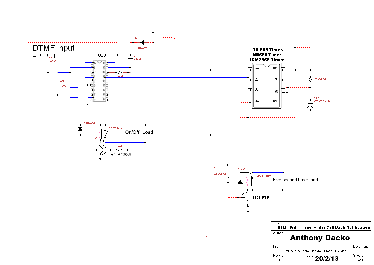
TS555 Timer
The operation of the circuit is straightforward. When a DTMF tone is sent to the decoder, pin 15 goes high for a brief period, which serves as an effective trigger by supplying a few volts to pin 2 of the...
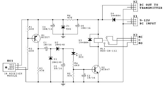
555 timer Door minder electronic project circuit diagram
This door minder electronic project is based on a 555 timer circuit and utilizes an infrared (IR) beam to monitor doorways, passageways, or any other designated area. When the IR beam is interrupted, a relay is activated, which can be...
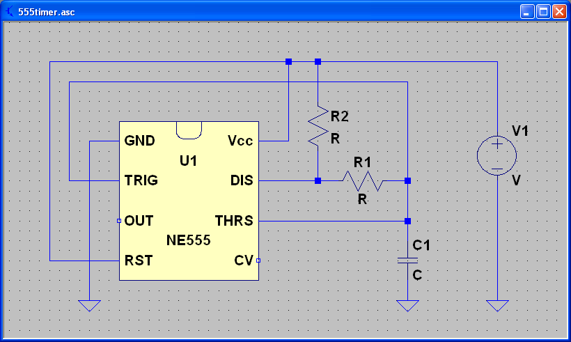
Capacitors and the 555 Timer
ECEN 2250 myDAQ Experiment Capacitors and the 555 Timer.
The experiment involving capacitors and the 555 timer within the ECEN 2250 myDAQ framework focuses on understanding the behavior of capacitors in electronic circuits and the functionality of the 555 timer as...
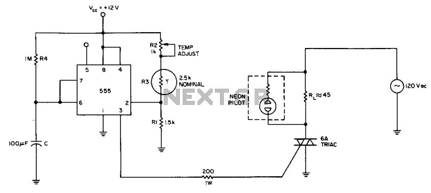
simple temperature controller
The internal comparator of the 555 timer, combined with a thermistor, creates a low-cost temperature controller. Resistor R2 establishes the temperature trip point.
The 555 timer is a versatile integrated circuit widely used in various applications, including timers, oscillators, and pulse...
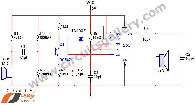
555 timer IC audio amplifier circuit schematics
This document discusses a simple project utilizing the 555 timer IC. The 555 timer IC can be configured as an audio amplifier using an astable multivibrator configuration. It performs pulse width modulation (PWM) on an audio signal. The current capacity...
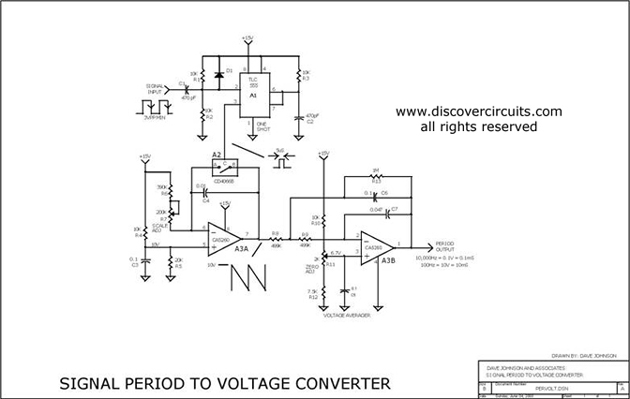
PULSE PERIOD TO VOLTAGE CONVERTER
This circuit is designed to convert a square wave input signal into a voltage output. The voltage produced is proportional to the time interval between the edges (period) of the signal, rather than its frequency. The operational range of the...
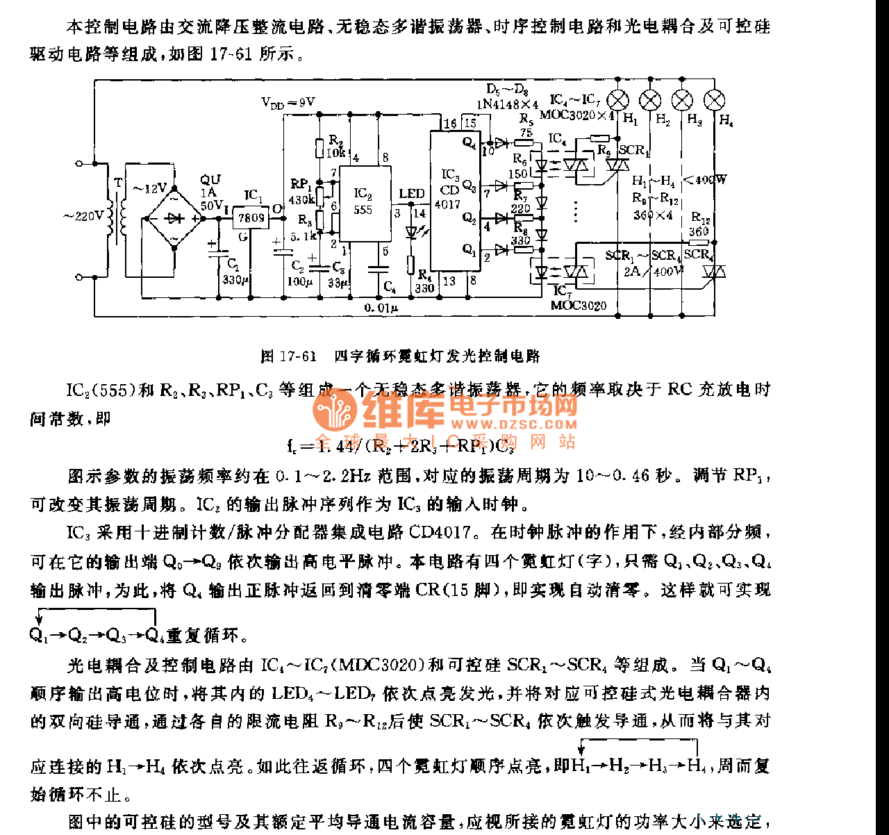
555 four words cycle neon light light control circuit
This control circuit consists of an AC step-down rectifier circuit, an astable multivibrator, a timing control circuit, an optocoupler circuit, and an SCR driving circuit, as illustrated in Figure 17-61. The astable multivibrator is formed using IC2 (555), resistors R2,...
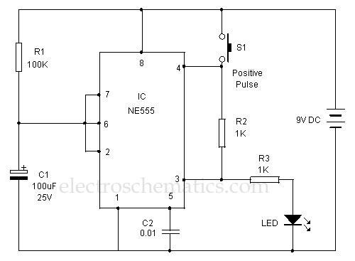
Positive Trigger Timer Circuit
This 555 timer is designed uniquely to provide a positive output through control over its reset pin. Typically, the 555 timer IC is triggered by applying a negative voltage.
The 555 timer is a versatile integrated circuit widely used in various...
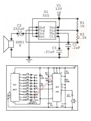
car sound generator schematic
An astable oscillator is constructed using a 555 timer, producing an alarm tone of 1.8 kHz that directly drives a speaker. This fundamental alarm circuit serves as a basis for various other projects in the book. Although the circuit is...