

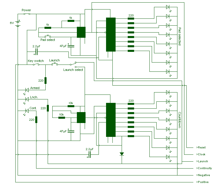

Model rocket launch controller
Eight LED`s are used to indicate the pad currently selected. These LED`s are connected to a decade counter, which sequences the LED`s when it receives a clock p...
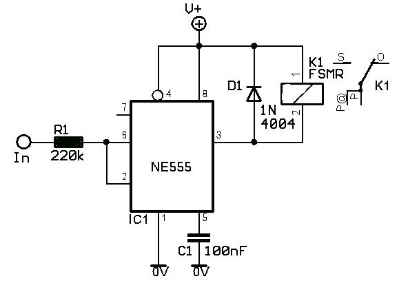
Voltage Controlled Switch with 555
The old and omnipresent NE555 can be very good at something it was not meant for: driving relays or other loads up to 200 mA. The picture shows an example circu...
Voltage Controlled Switch with 555
The old and omnipresent NE555 can be very good at something it was not meant for: driving relays or other loads up to 200 mA. The picture shows an example circu...
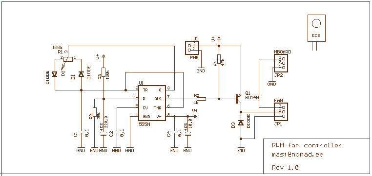
Simple PWM controller
This 555 timer based PWM controller features almost 0..100% pulse width regulation using R1, while keeping the oscillator frequency relatively stable. The frequ...
Simple PWM controller
This 555 timer based PWM controller features almost 0..100% pulse width regulation using R1, while keeping the oscillator frequency relatively stable. The frequ...
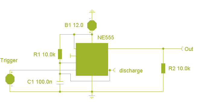
NE555 Basic Monostable
Here the popular 555 timing IC, is wired as a monostable. The timing period is precise and equivalent to:-
1.1 x R1 x C1
With component values shown thi...
NE555 Basic Monostable
Here the popular 555 timing IC, is wired as a monostable. The timing period is precise and equivalent to:-
1.1 x R1 x C1
With component values shown thi...
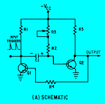
Monostable multivibrator schematic
The schematic for a monostable multivibrator is shown in figure 3-11. Like the astable multivibrator, one transistor conducts and the other cuts off when the ci...
Monostable multivibrator schematic
The schematic for a monostable multivibrator is shown in figure 3-11. Like the astable multivibrator, one transistor conducts and the other cuts off when the ci...
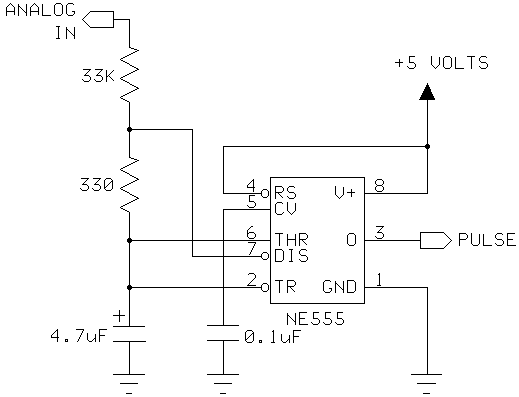
555 Timer as an A/D converter
I had a Basic Stamp project that needed to measure a nominal 12 volt battery, and I wanted a simple solution. This is the simplest I could come up with. The 555...
555 Timer as an A/D converter
I had a Basic Stamp project that needed to measure a nominal 12 volt battery, and I wanted a simple solution. This is the simplest I could come up with. The 555...