


Might Diamonds
#diamond buffer
#transistors
#resistors
#circuit modification
#audio buffer
#signal processing
#low component count
#blog reference
#electronic design
#buffer amplifier
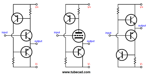
Description: The diamond buffer circuit consists of four transistors and four resistors, making it a simple design. However, it has been criticized for its limited performance. Previous discussions about the circuit and its modifications can be found in earlier blogs. A significant modification was intended for discussion, addressing a major issue with the basic diamond buffer circuit: its inadequate performance under heavy load, which is essential for a buffer. Manufacturers of operational amplifiers (OpAmps) have developed solutions to this problem, such as the circuit in the OPA633. In this design, when the input stage is capable of driving the output transistors, the nested transistors remain inactive. However, if the input stage struggles, these transistors activate to assist the output transistors. The LMH6321 addresses this issue differently by employing a robust dual push-pull input stage that effectively drives the output transistors. Although the actual circuit is more complex, the protection diodes have been omitted for clarity. Each output transistor is supported by its own three-transistor push-pull driver stage. These intricate designs are essential for OpAmps as large capacitors cannot be accommodated in their compact packages. Conversely, a diamond buffer using discrete components allows for the incorporation of larger electrolytic capacitors. Adding just one large capacitor significantly enhances the diamond buffer's performance by transforming the input stage into a push-pull configuration, effectively linking the two emitters and enabling both input transistors to collaboratively drive the output transistors. Despite this enhancement, further improvements are still necessary. The issue is linked to class-AB operation, where the output impedance doubles when one output transistor turns off, causing distortion perceived as a scratchy sound. Various complex topologies were tested to address this, with some success detailed in earlier blogs. Ultimately, a straightforward solution emerged: adding another capacitor. This capacitor, in AC terms, connects the emitters of the output transistors, maintaining a consistent output impedance of approximately 5 ohms, even when one transistor is inactive. Although the gm-doubling effect of the output transistors persists, it is negligible compared to the 10-ohm emitter resistances, making it less impactful. The difference in output impedance when both transistors are conducting versus when only one is active is minimal, reducing distortion. A SPICE simulation illustrates the performance comparison between the conventional diamond buffer and the modified version with additional capacitors, both designed to output 1Vpk into 32 ohms at 1kHz.
The diamond buffer circuit is a straightforward design that utilizes four transistors and four resistors. Despite its simplicity, it has faced criticism for not performing well under high load conditions. The core issue with the original diamond buffer is its inability to maintain performance when subjected to demanding operational scenarios. This limitation is particularly significant for a buffer, which ideally should deliver consistent output regardless of load variations.
In addressing these limitations, operational amplifier manufacturers have devised innovative solutions. The OPA633 circuit exemplifies this approach, incorporating a design where the input stage can effectively drive the output transistors. In this configuration, the nested transistors remain inactive under normal operating conditions but activate when the input stage experiences difficulty. This clever design ensures that the output transistors receive the necessary drive under varying load conditions.
Similarly, the LMH6321 adopts a different strategy, featuring a robust dual push-pull input stage capable of driving the output transistors to their full potential. While the overall complexity of the circuit is greater, the omission of protection diodes provides a clearer understanding of the topology. Each output transistor is managed by its dedicated three-transistor push-pull driver stage, a necessity in operational amplifiers where space constraints limit the inclusion of larger capacitors.
In contrast, a diamond buffer constructed from discrete components allows for the integration of larger electrolytic capacitors, which can significantly enhance performance. The addition of a single large capacitor can transform the input stage into a push-pull configuration, effectively linking the emitters of the input transistors. This configuration allows both transistors to work in unison, improving the driving capability of the output transistors.
Despite these enhancements, further refinements are required to achieve optimal performance. The output impedance issue during class-AB operation remains a concern, as the impedance can double when one output transistor turns off, resulting in audible distortion. Various complex topologies were explored to mitigate this issue, with some yielding positive results.
Ultimately, a simple yet effective solution was identified: the introduction of an additional capacitor. This capacitor connects the emitters of the output transistors in AC terms, ensuring that the output impedance remains relatively constant, even when one transistor is inactive. While the gm-doubling effect of the output transistors persists, its impact is minimal compared to the overall output impedance presented by the emitter resistances.
A comparative analysis using SPICE simulation illustrates the performance differences between the conventional diamond buffer and the modified version with the additional capacitors. Both circuits are tested under identical conditions, outputting 1Vpk into a 32-ohm load at 1kHz, showcasing the improvements achieved through the modifications.With only four transistors and four resistors, the diamond buffer does not require much. Some harsh critics would add that it does not deliver much either. I have covered the circuit and its modification here before, for example in Blog 232 and Blog 187. But for over a year, I have been meaning to write about a significant modification to the basic circuit that I came up with. In fact, I planned on including it in my last post. Here is the big problem with the naked diamond buffer circuit: it works great as long as you do not ask to work hard, which is a tad bit sad, as that`s exactly what we want from a buffer. The makers of OpAmps know about this problem and they have come up with some clever workarounds, such as this circuit found in the OPA633.
As long as the input stage can handle driving the output transistors, the two transistors nested inside do nothing; in fact, they are not even turned on. But once the input stage falters, they begin conducting and take over the task of driving the output transistors.
Clever, very clever. The LMH6321 tackles the same problem in a different way: it builds a very robust, dual, push-pull, input stage that can easily drive the output transistors to full output. (The actual circuit is more complex, but I erased the protection diodes to make the topology more readily apprehensible.
) Each output transistor gets its own three-transistor, push-pull, driver stage. These elaborate topologies are necessary in an OpAmp, as it is impossible to include large-valued capacitors within the OpAmp`s small plastic package. On the other hand, if we build up a diamond buffer out of discrete transistors and resistors, we can add as many big electrolytic capacitors as we please.
Indeed, just adding one big electrolytic capacitor makes a big improvement in the diamond`s performance. This added capacitor effectively transforms the input stage into a push-pull one, as the 1k µF capacitor effectively ties the two emitters together, so both input transistor work as a team to to drive the output transistors.
Still, even after this modification, the diamond does not completely please; it still needs improvement. My reasoning was that the problem lay in the class-AB operation and that when one output transistor cut off, the diamond`s output impedance doubled, causing a glitch in the output waveform, which the ear hears as scratchy sounding.
I then set about fixing the problem with elaborate topologies. Some of them actually worked. See Blog 177 for more details. After much experimenting, I found a simple solution: one more capacitor. The added capacitor, in AC terms, shorts the two output transistor emitters together, so even when one transistor cuts off, the output impedance remains fairly constant, about 5 ohms. Wait a minute, what about the gm-doubling effect of the output transistors Well, the effect is still there, but it is so small compared to the 10-ohm emitter resistor resistances that it is swamped out of the equation.
In other words, the output transistor emitters present so low an output impedance that halving it when both are conducting, say 0. 05 ohms, and switching to 0. 1 ohms when only one conducts, makes little difference when added to the 5-ohm resistance. For example, 5. 05 ohms versus 5. 1 ohms is not as startling to the ear as 5. 05 ohms versus 10. 1 ohms without the extra capacitor. Okay, it`s interesting but does it work The answer is not an easy one to give. Here is an example, the following graph shows a SPICE simulation Fourier graph of the conventional diamond versus the Mighty Diamond, with all the same parts except for the two added capacitors, which define the Mighty version.
The circuits were required to put out 1Vpk into 32 ohms at 1kHz. Except
The diamond buffer circuit is a straightforward design that utilizes four transistors and four resistors. Despite its simplicity, it has faced criticism for not performing well under high load conditions. The core issue with the original diamond buffer is its inability to maintain performance when subjected to demanding operational scenarios. This limitation is particularly significant for a buffer, which ideally should deliver consistent output regardless of load variations.
In addressing these limitations, operational amplifier manufacturers have devised innovative solutions. The OPA633 circuit exemplifies this approach, incorporating a design where the input stage can effectively drive the output transistors. In this configuration, the nested transistors remain inactive under normal operating conditions but activate when the input stage experiences difficulty. This clever design ensures that the output transistors receive the necessary drive under varying load conditions.
Similarly, the LMH6321 adopts a different strategy, featuring a robust dual push-pull input stage capable of driving the output transistors to their full potential. While the overall complexity of the circuit is greater, the omission of protection diodes provides a clearer understanding of the topology. Each output transistor is managed by its dedicated three-transistor push-pull driver stage, a necessity in operational amplifiers where space constraints limit the inclusion of larger capacitors.
In contrast, a diamond buffer constructed from discrete components allows for the integration of larger electrolytic capacitors, which can significantly enhance performance. The addition of a single large capacitor can transform the input stage into a push-pull configuration, effectively linking the emitters of the input transistors. This configuration allows both transistors to work in unison, improving the driving capability of the output transistors.
Despite these enhancements, further refinements are required to achieve optimal performance. The output impedance issue during class-AB operation remains a concern, as the impedance can double when one output transistor turns off, resulting in audible distortion. Various complex topologies were explored to mitigate this issue, with some yielding positive results.
Ultimately, a simple yet effective solution was identified: the introduction of an additional capacitor. This capacitor connects the emitters of the output transistors in AC terms, ensuring that the output impedance remains relatively constant, even when one transistor is inactive. While the gm-doubling effect of the output transistors persists, its impact is minimal compared to the overall output impedance presented by the emitter resistances.
A comparative analysis using SPICE simulation illustrates the performance differences between the conventional diamond buffer and the modified version with the additional capacitors. Both circuits are tested under identical conditions, outputting 1Vpk into a 32-ohm load at 1kHz, showcasing the improvements achieved through the modifications.With only four transistors and four resistors, the diamond buffer does not require much. Some harsh critics would add that it does not deliver much either. I have covered the circuit and its modification here before, for example in Blog 232 and Blog 187. But for over a year, I have been meaning to write about a significant modification to the basic circuit that I came up with. In fact, I planned on including it in my last post. Here is the big problem with the naked diamond buffer circuit: it works great as long as you do not ask to work hard, which is a tad bit sad, as that`s exactly what we want from a buffer. The makers of OpAmps know about this problem and they have come up with some clever workarounds, such as this circuit found in the OPA633.
As long as the input stage can handle driving the output transistors, the two transistors nested inside do nothing; in fact, they are not even turned on. But once the input stage falters, they begin conducting and take over the task of driving the output transistors.
Clever, very clever. The LMH6321 tackles the same problem in a different way: it builds a very robust, dual, push-pull, input stage that can easily drive the output transistors to full output. (The actual circuit is more complex, but I erased the protection diodes to make the topology more readily apprehensible.
) Each output transistor gets its own three-transistor, push-pull, driver stage. These elaborate topologies are necessary in an OpAmp, as it is impossible to include large-valued capacitors within the OpAmp`s small plastic package. On the other hand, if we build up a diamond buffer out of discrete transistors and resistors, we can add as many big electrolytic capacitors as we please.
Indeed, just adding one big electrolytic capacitor makes a big improvement in the diamond`s performance. This added capacitor effectively transforms the input stage into a push-pull one, as the 1k µF capacitor effectively ties the two emitters together, so both input transistor work as a team to to drive the output transistors.
Still, even after this modification, the diamond does not completely please; it still needs improvement. My reasoning was that the problem lay in the class-AB operation and that when one output transistor cut off, the diamond`s output impedance doubled, causing a glitch in the output waveform, which the ear hears as scratchy sounding.
I then set about fixing the problem with elaborate topologies. Some of them actually worked. See Blog 177 for more details. After much experimenting, I found a simple solution: one more capacitor. The added capacitor, in AC terms, shorts the two output transistor emitters together, so even when one transistor cuts off, the output impedance remains fairly constant, about 5 ohms. Wait a minute, what about the gm-doubling effect of the output transistors Well, the effect is still there, but it is so small compared to the 10-ohm emitter resistor resistances that it is swamped out of the equation.
In other words, the output transistor emitters present so low an output impedance that halving it when both are conducting, say 0. 05 ohms, and switching to 0. 1 ohms when only one conducts, makes little difference when added to the 5-ohm resistance. For example, 5. 05 ohms versus 5. 1 ohms is not as startling to the ear as 5. 05 ohms versus 10. 1 ohms without the extra capacitor. Okay, it`s interesting but does it work The answer is not an easy one to give. Here is an example, the following graph shows a SPICE simulation Fourier graph of the conventional diamond versus the Mighty Diamond, with all the same parts except for the two added capacitors, which define the Mighty version.
The circuits were required to put out 1Vpk into 32 ohms at 1kHz. Except
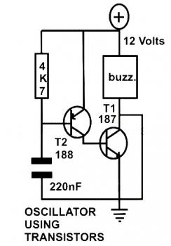
basic oscillator circuit using two
This schematic diagram represents a basic oscillator circuit utilizing two transistors. When the transistors and several passive components are connected as illustrated, the circuit begins to oscillate. The oscillation frequency can be modified by altering the values of either the...
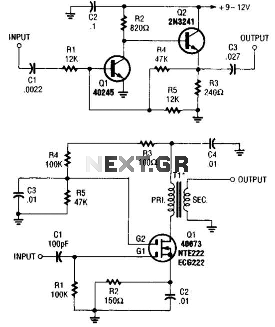
Buffer Amplifiers Circuit
These two buffer/amplifiers have been effectively utilized with variable frequency oscillators (VFOs): one (depicted in A) is constructed using a pair of bipolar NPN transistors, while the other (illustrated in B) is designed around a dual-gate MOSFET.
The first buffer/amplifier, utilizing...
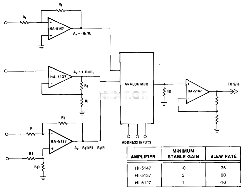
Buffer-amplifier-for-multiplexers
The precision input characteristics of the HA-5147 simplify system error budgets, while its speed and drive capabilities enable fast charging of the multiplexer’s output capacitance. This speed eliminates increased multiplexer acquisition time, which can be induced by amplifiers with more...
intercom circuit with transistors
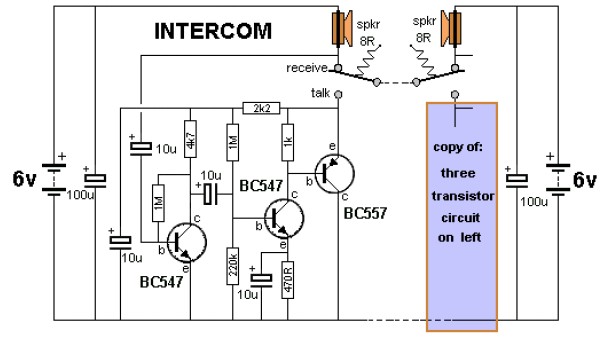
The key to avoiding instability (motor-boating) in a high-gain circuit is to power the speaker using a separate power supply. This circuit design allows for the connection of one or two additional stations. It is recommended to construct the circuit...
motorola hi fi power
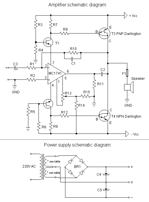
The first step is to measure the amplification factor of the end transistors (T3 and T4), known as the hfe. If their difference exceeds 30%, the amplifier will produce unclear sound. In this case, MJ3001 and MJ2501 transistors were used,...
discussing output stage of square wave
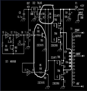
The circuit includes 10K resistors at the bases of the transistors and 1K resistors at the collectors. It is essential to retain these components when relocating the transistors, as omitting the 10K resistors could result in transistor failure, and without...

buffer amplifiers
This class of amplifier is designed to follow low-level stages, such as a crystal oscillator. An oscillator requires an intermediate stage to prevent loading, ensuring that the input impedance is sufficiently high to avoid significant loading on the oscillator. This...
Interpolating Scanner Circuit
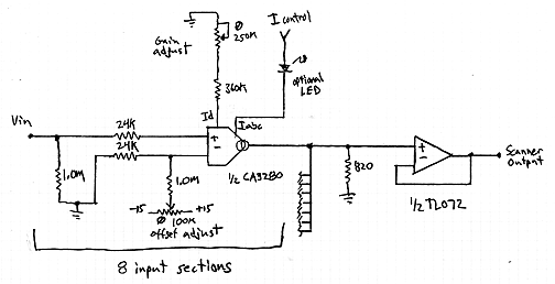
This design is for an interpolating scanner, a circuit featuring multiple signal inputs, a control voltage input, and a signal output. The output selectively transitions between inputs, smoothly fading from one to the next as the control voltage increases. A...
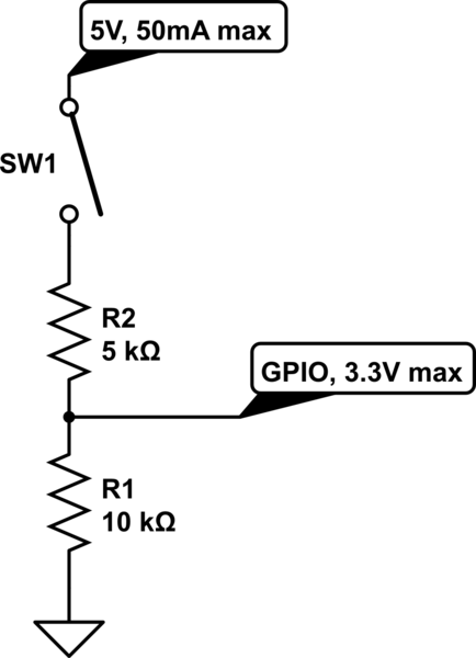
resistors Current flows from the source towards the sink
The circuit is designed to limit the maximum voltage between the GPIO input pin and the current source to 3.3V. This is achieved through a voltage divider configuration where the voltage across the 10K resistor is 3.3V, while the voltage...