


Turn A Compensated Current Sink Into A Common Emitter (CE) Amplifier
#common emitter
#current sink
#amplifier
#beta-compensated
#temperature-compensated
#biasing
#transistor
#CE amplifier
#stable bias
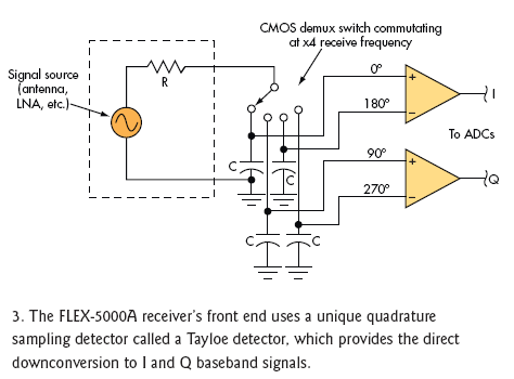
Description: By adding only a few components, a temperature- and beta-compensated current sink can be converted into a common-emitter (CE) amplifier that maintains a stable biased operating point. This design concept will demonstrate the process.
To implement this design, the primary goal is to utilize a temperature- and beta-compensated current sink as the foundational element for the common-emitter amplifier configuration. The current sink will provide a stable biasing condition essential for the proper operation of the CE amplifier.
The circuit typically consists of a bipolar junction transistor (BJT) configured in the common-emitter arrangement. This configuration allows for voltage amplification while ensuring that the operating point remains stable across varying temperatures and transistor beta (β) values.
Key components involved in this design include:
1. **Transistor**: A BJT is selected based on the desired gain and frequency response. The emitter resistor is crucial for thermal stability and biasing.
2. **Current Sink**: The current sink is designed to provide a constant current to the base of the transistor. This can be achieved using a simple resistor-capacitor (RC) network or more advanced configurations such as Wilson current mirrors or Widlar current sources.
3. **Biasing Resistors**: Resistors are employed to set the base bias voltage, ensuring that the transistor operates in the active region. These resistors also help in stabilizing the operating point against variations in temperature and beta.
4. **Coupling Capacitors**: To prevent DC bias from affecting subsequent stages, coupling capacitors are used to connect the amplifier to other circuit stages while allowing AC signals to pass through.
5. **Bypass Capacitor**: A bypass capacitor may be added across the emitter resistor to enhance gain at higher frequencies by reducing the effect of the emitter resistor on AC signals.
The overall design emphasizes simplicity and efficiency, allowing for easy integration into various applications requiring stable amplification. By carefully selecting component values and configurations, the amplifier can achieve desired performance metrics, including gain, bandwidth, and linearity, while maintaining robustness against environmental variations.By adding only a few components, you can turn a temperature- and beta-compensated current sink into a common-emitter (CE) amplifier that maintains a stable biased operating point. This Idea for Design will show you how
To implement this design, the primary goal is to utilize a temperature- and beta-compensated current sink as the foundational element for the common-emitter amplifier configuration. The current sink will provide a stable biasing condition essential for the proper operation of the CE amplifier.
The circuit typically consists of a bipolar junction transistor (BJT) configured in the common-emitter arrangement. This configuration allows for voltage amplification while ensuring that the operating point remains stable across varying temperatures and transistor beta (β) values.
Key components involved in this design include:
1. **Transistor**: A BJT is selected based on the desired gain and frequency response. The emitter resistor is crucial for thermal stability and biasing.
2. **Current Sink**: The current sink is designed to provide a constant current to the base of the transistor. This can be achieved using a simple resistor-capacitor (RC) network or more advanced configurations such as Wilson current mirrors or Widlar current sources.
3. **Biasing Resistors**: Resistors are employed to set the base bias voltage, ensuring that the transistor operates in the active region. These resistors also help in stabilizing the operating point against variations in temperature and beta.
4. **Coupling Capacitors**: To prevent DC bias from affecting subsequent stages, coupling capacitors are used to connect the amplifier to other circuit stages while allowing AC signals to pass through.
5. **Bypass Capacitor**: A bypass capacitor may be added across the emitter resistor to enhance gain at higher frequencies by reducing the effect of the emitter resistor on AC signals.
The overall design emphasizes simplicity and efficiency, allowing for easy integration into various applications requiring stable amplification. By carefully selecting component values and configurations, the amplifier can achieve desired performance metrics, including gain, bandwidth, and linearity, while maintaining robustness against environmental variations.By adding only a few components, you can turn a temperature- and beta-compensated current sink into a common-emitter (CE) amplifier that maintains a stable biased operating point. This Idea for Design will show you how
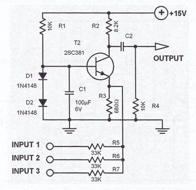
One Transistor Audio Mixer
The simplest one-transistor audio mixer circuit diagram available. It utilizes a single transistor and can accommodate multiple audio signals, limited only by the user's budget. BC10.
The one-transistor audio mixer circuit is a fundamental design that demonstrates the principles of audio...
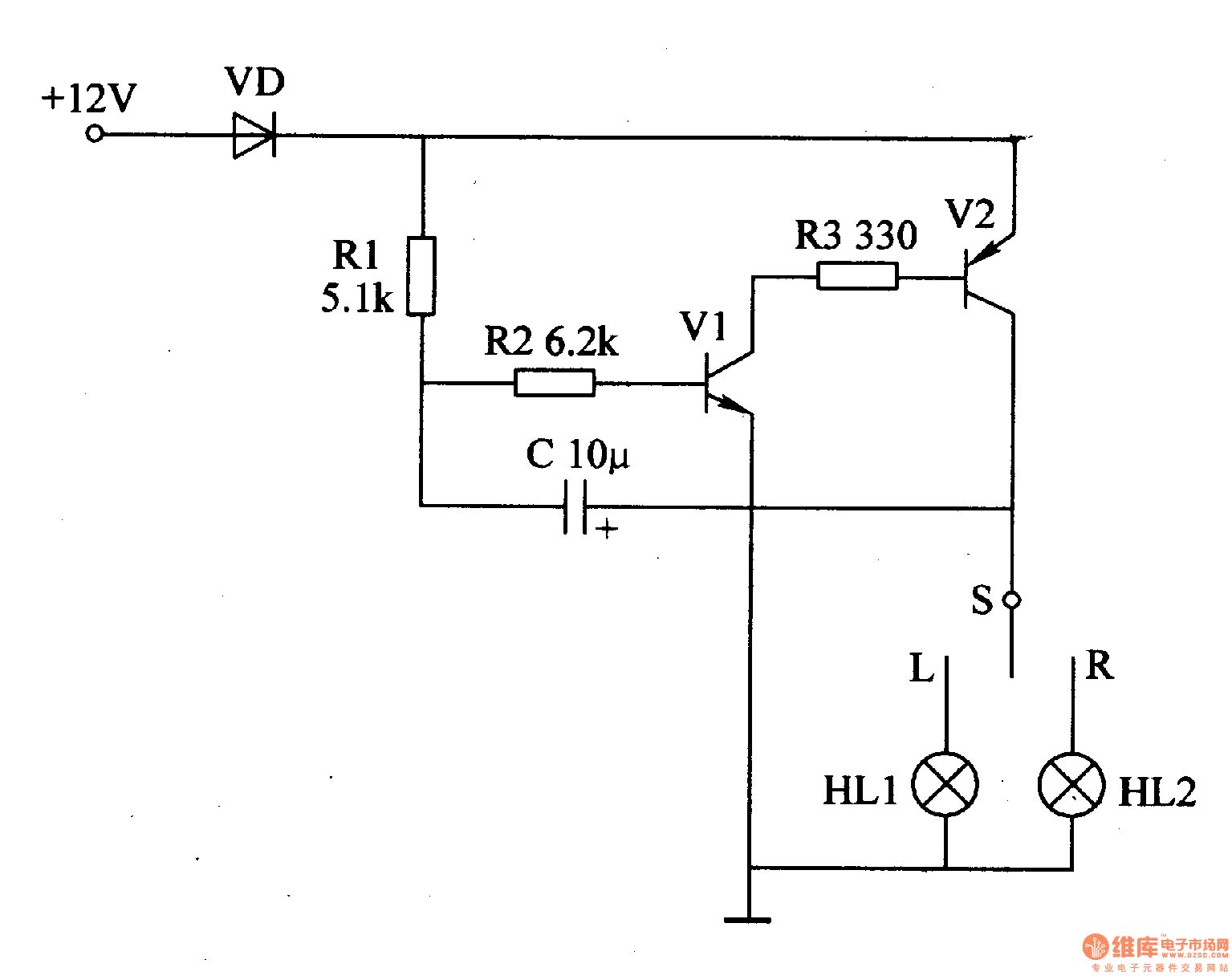
Motor vehicle steering flasher 12
The motor vehicle steering flasher described in the example utilizes high-power transistors as electronic switches, and the circuit is simple and easy to construct. The motor vehicle steering flasher consists of the flash circuit with resistors R1-R3, a capacitor C,...
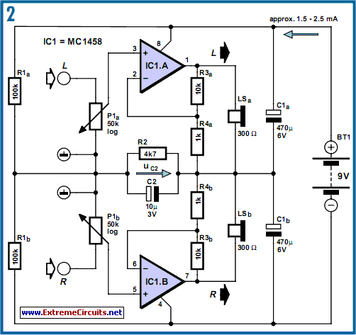
DC-Coupled Audio Amplifier circuit
Designs for audio amplifiers with DC coupling to the load are not frequently seen today, despite offering distinct advantages.
Audio amplifiers that employ DC coupling to the load provide several benefits that can enhance performance in specific applications. In traditional audio...
Precision current sink
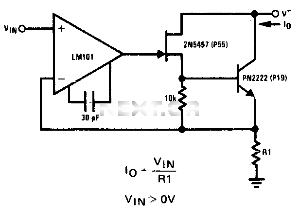
The 2N5457 JFET and PN2222 bipolar transistor exhibit high output impedance. Employing Rl as a current sensing resistor to feedback into the LM101 operational amplifier yields significant loop gain for negative feedback, thereby improving the circuit's capability as a current...
Low Capacitance High Impedance Amplifier Circuit Using Transistor
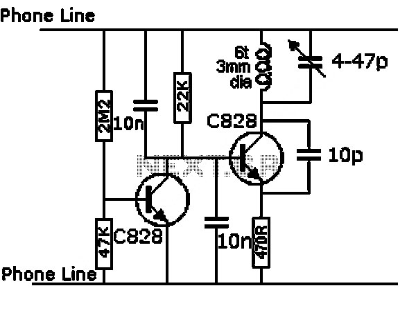
This series-feedback configuration of components provides a high input impedance and stable, wide-band gain video amplifier suitable for general-purpose applications. Below is the schematic representation of the circuit.
The described video amplifier circuit employs a series-feedback topology, which is instrumental in...
voltage transistor loop to limit the current
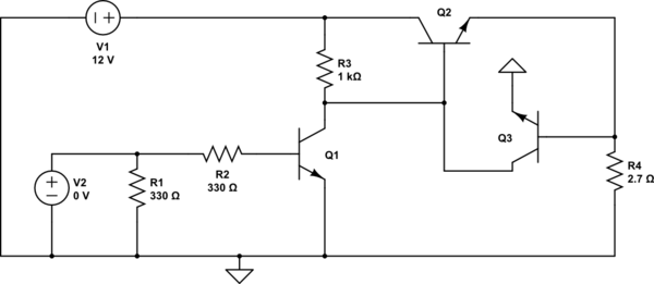
The second transistor (T2) is activated by the current passing through the resistor (R1). When a DALI slave unit is connected, this current matches the current flowing through the power transistor (T1). The resistor's value is selected so that when...
Astable Multivibrator with 2 Transistors
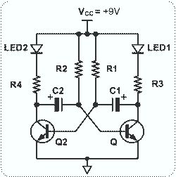
This circuit is straightforward and easy to construct, utilizing two transistors as active components along with several passive components such as resistors, capacitors, and two LEDs. The circuit employs the MPS2222 transistor, though any NPN type transistor can be used...
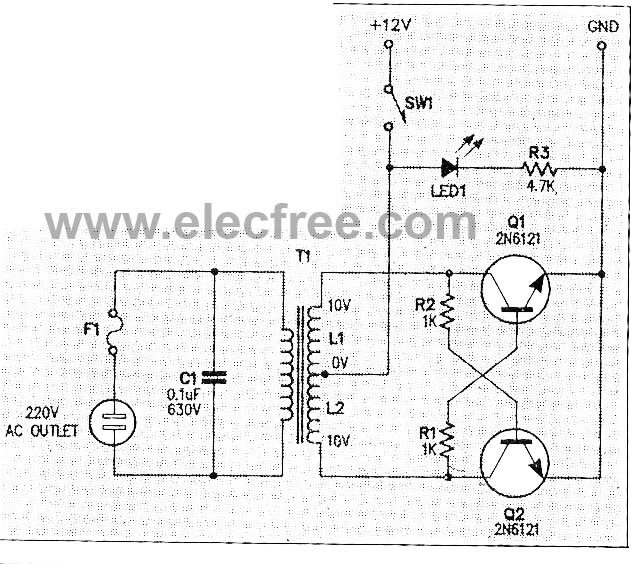
Micro Inverter by 2N6121
This micro inverter is a small-sized device that modifies energy from a battery, producing an output voltage of approximately 220V AC at 50Hz. The circuit comprises two transistors that function as a pulse oscillator or square wave generator, driving a...
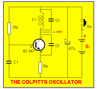
TALKING ELECTRONICS BEC
This circuit is easily identifiable by three equal-value capacitors and two equal-value resistors connected to the base of the transistor. The output signal of a transistor in COMMON EMITTER mode is FALLING when the input signal is RISING, which results...