


1.8V DC DC converter electronic circuit desicgn using ISL8012 IC
#DC DC converter
#step-down
#ISL8012
#voltage regulation
#synchronous converter
#2A output
#2.7V-5.5V input
#power management
#current control
#monolithic
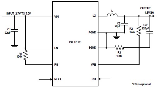
Description: The ISL8012 is a high-efficiency, monolithic, synchronous step-down DC-DC converter that can be designed into a simple electronic project. It supports a maximum continuous output current of up to 2A from an input supply range of 2.7V to 5.5V. The ISL8012 employs a current control architecture, enabling very low duty cycle operation at high frequencies, resulting in fast transient response and excellent loop stability. It integrates a pair of low ON-resistance P-Channel and N-Channel internal MOSFETs to maximize efficiency and minimize the external component count. This DC-DC converter project requires very few electronic parts, as illustrated in the schematic circuit diagram. The device features 100% duty-cycle operation, which allows for a dropout voltage of less than 240mV at 2A output current. The high 1MHz pulse-width modulation (PWM) switching frequency facilitates the use of small external components. The ISL8012 can be configured for either discontinuous or forced continuous operation at light loads. Forced continuous operation helps reduce noise and RF interference, while discontinuous mode enhances efficiency by minimizing switching losses under light load conditions. Additionally, fault protection is incorporated through internal current limiting during short circuit and overcurrent situations, an output overvoltage comparator, and an over-temperature monitoring circuit.
The ISL8012 DC-DC converter circuit is designed to efficiently convert a variable input voltage within the specified range to a stable output voltage while maintaining high performance. The schematic typically includes essential components such as input and output capacitors, a feedback network for voltage regulation, and the necessary inductors that work in conjunction with the internal MOSFETs to achieve the desired output characteristics.
The input capacitors stabilize the input voltage and reduce voltage ripple, while the output capacitors smooth the output voltage and provide transient response during load changes. The feedback network often consists of resistors configured to set the output voltage and ensure proper regulation. The inductor value is critical for determining the current ripple and overall efficiency of the converter, and it must be chosen based on the desired output current and switching frequency.
The integration of fault protection mechanisms ensures the reliability of the circuit. During overcurrent conditions, the internal current limiting feature protects the converter and the load from excessive current that could potentially cause damage. The output overvoltage comparator serves to safeguard against unexpected voltage spikes, while the over-temperature monitor prevents overheating, thereby enhancing the longevity and safety of the device.
Overall, the ISL8012 provides a robust solution for applications requiring efficient power management with minimal external components, making it suitable for a wide range of electronic devices and systems.Using the ISL8012 high efficiency, monolithic, synchronous step-down DC DC converter can be designed a very simple DC DC converter electronic project that can support a maximum output current up to 2A (continuous output current ) from a 2. 7V to 5. 5V input supply. ISL8012 uses a current control architecture to deliver very low duty cycle operation at high frequency with fast transient response and excellent loop stability. The ISL8012 integrates a pair of low ON-resistance P-Channel and N-Channel internal MOSFETs to maximize efficiency and minimize external component count ( as you can see in the schematic circuit diagram this DC DC converter electronic project require extreme low electronic parts ). The 100% duty-cycle operation allows less than 240mV dropout voltage at 2A output current. High 1MHz pulse-width modulation (PWM) switching frequency allows the use of small external components.
The ISL8012 can be configured for discontinuous or forced continuous operation at light load. Forced continuous operation reduces noise and RF interference while discontinuous mode provides high efficiency by reducing switching losses at light loads. Fault protection is provided by internal current limiting during short circuit and overcurrent conditions, an output over voltage comparator and over-temperature monitor circuit.
The ISL8012 DC-DC converter circuit is designed to efficiently convert a variable input voltage within the specified range to a stable output voltage while maintaining high performance. The schematic typically includes essential components such as input and output capacitors, a feedback network for voltage regulation, and the necessary inductors that work in conjunction with the internal MOSFETs to achieve the desired output characteristics.
The input capacitors stabilize the input voltage and reduce voltage ripple, while the output capacitors smooth the output voltage and provide transient response during load changes. The feedback network often consists of resistors configured to set the output voltage and ensure proper regulation. The inductor value is critical for determining the current ripple and overall efficiency of the converter, and it must be chosen based on the desired output current and switching frequency.
The integration of fault protection mechanisms ensures the reliability of the circuit. During overcurrent conditions, the internal current limiting feature protects the converter and the load from excessive current that could potentially cause damage. The output overvoltage comparator serves to safeguard against unexpected voltage spikes, while the over-temperature monitor prevents overheating, thereby enhancing the longevity and safety of the device.
Overall, the ISL8012 provides a robust solution for applications requiring efficient power management with minimal external components, making it suitable for a wide range of electronic devices and systems.Using the ISL8012 high efficiency, monolithic, synchronous step-down DC DC converter can be designed a very simple DC DC converter electronic project that can support a maximum output current up to 2A (continuous output current ) from a 2. 7V to 5. 5V input supply. ISL8012 uses a current control architecture to deliver very low duty cycle operation at high frequency with fast transient response and excellent loop stability. The ISL8012 integrates a pair of low ON-resistance P-Channel and N-Channel internal MOSFETs to maximize efficiency and minimize external component count ( as you can see in the schematic circuit diagram this DC DC converter electronic project require extreme low electronic parts ). The 100% duty-cycle operation allows less than 240mV dropout voltage at 2A output current. High 1MHz pulse-width modulation (PWM) switching frequency allows the use of small external components.
The ISL8012 can be configured for discontinuous or forced continuous operation at light load. Forced continuous operation reduces noise and RF interference while discontinuous mode provides high efficiency by reducing switching losses at light loads. Fault protection is provided by internal current limiting during short circuit and overcurrent conditions, an output over voltage comparator and over-temperature monitor circuit.
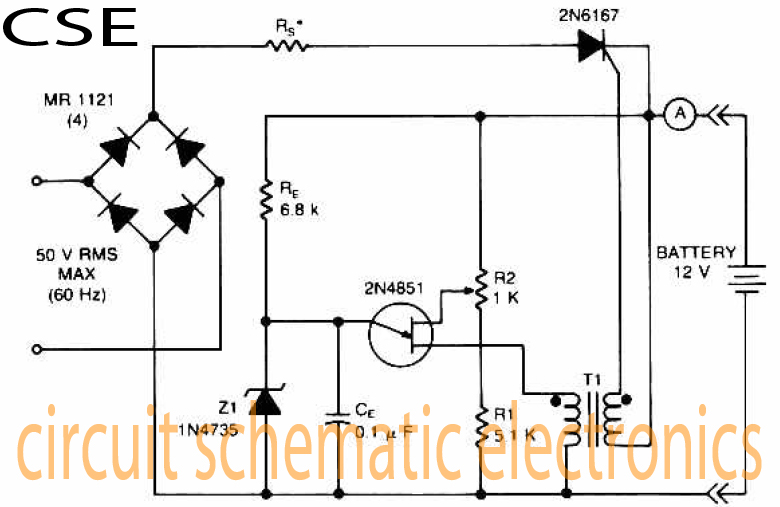
Variable charger circuit Schematic Diagram
The accumulator charger circuit must provide a voltage that matches the specifications of the batteries being charged. For a 12-volt accumulator, the output voltage should not exceed 12 volts, nor should it fall significantly below this threshold. Failure to maintain...
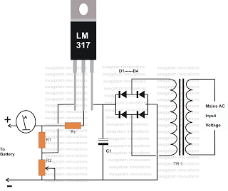
how to make inexpensive current
Charging any type of rechargeable battery is critical and requires attention, particularly regarding the current or rate at which the battery is charged. This factor is essential for maintaining the battery's lifespan and efficiency over time. The circuit diagram presented...
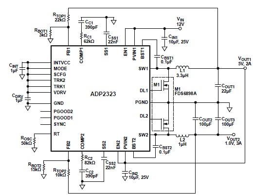
ADP2323 high current DC DC converter circuit design electronic project
The ADP2323 DC-DC converter is designed to deliver two output voltages with specified maximum output currents. The first channel provides a 5-volt output with a maximum current of 2 Amperes, while the second channel supplies 1 volt with a maximum...
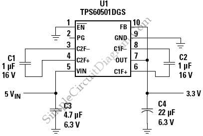
Step-Down Charge Pump Regulator for USB Powered Devices
This is a circuit of a step-down charge pump regulator for USB-powered devices. The critical design parameter of this circuit is the circuit area.
The step-down charge pump regulator is designed to efficiently convert a higher input voltage from USB...
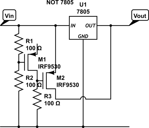
power Voltage supply clipping to <=3.3V
Supply it with a Li-Ion cell, which has a voltage range of 2.7 to 4.2V. The complexity of a buck/boost converter is not desired. While it is possible to regulate the voltage down to anything below 2.5V, it would be...
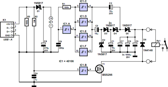
Computer Off Switch
How often does it happen that a user shuts down Windows and then forgets to turn off the computer? This circuit automates that process. After Windows is shut down, a click occurs a second later, disconnecting the PC from the...
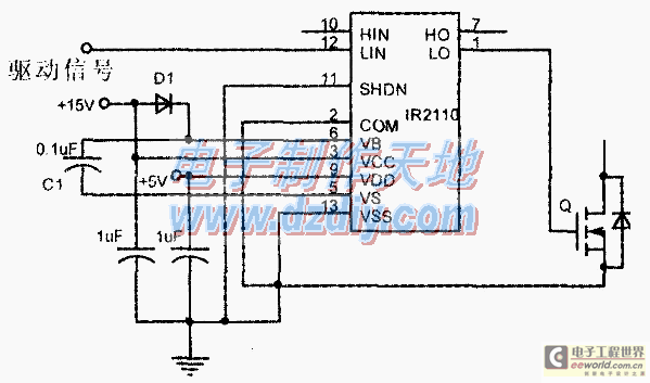
Design and making of the stabilized voltage supply of switch
Under the loading condition of the resistance, the output voltage (Uo) variable range is from 30V to 36V, with a maximum output current (Imax) of 2A. When the input voltage (U2) changes from 15V to 21V, the voltage regulation factor...
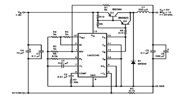
5V 1A Step Down Switching Regulator using LM2524D and Datasheet
The schematic diagram below illustrates a 5V/1A Step-Down Switching Regulator utilizing the LM2524D Regulating Pulse Width Modulator (PWM). Additional parameters, PC board layout, stuffing diagram, and more information can be found in the LM2524D datasheet.
The circuit design features the LM2524D,...
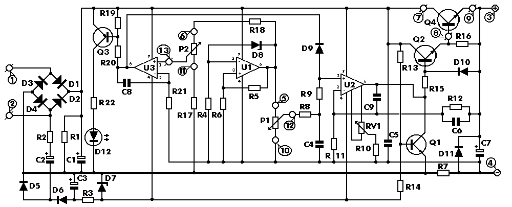
0-30 VDC Stabilized Power Supply with Current Control 0.002-3 A
The circuit begins with a step-down mains transformer featuring a secondary winding rated at 24 V/3 A, which connects across the input points at pins 1 and 2. The quality of the output supply is directly related to the transformer's...