


1000W AC power supply automatic voltage regulator circuit
#AC power supply
#automatic voltage regulator
#servo motor
#transistor
#diode
#1000W
#power management
#circuit protection
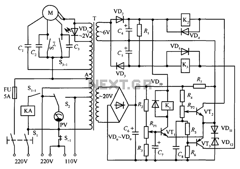
Description: The circuit illustrated in the figure features an automatic voltage regulator (T) that utilizes a servo motor to ensure a constant output voltage. The transistors used are VT1 and VT2 (3DK9C, with a range of 65 to 85) and VT3 (3AX818, with a range of 60 to 80). The diodes include VD2, VD3, and VD6 through VD9 (1N4002), while VD4, VD5, and VD10 are 1N4148 diodes. VD11 is an IN4001 diode, and the light-emitting diode VD1 is a BT304. The Zener diode VD12 is a 2CW119. The capacitors consist of C1 (1 µF, 400V), C2 and C3 (0.1 µF, 250V), C4 and C5 (220 µF, 25V), C6 (470 µF, 50V), and C7 and C8 (47 µF, 50V). The resistances are R1 (10kΩ), R2 and R7 (510Ω), R3 and R6 (2.7kΩ), R4 (470Ω), and R5 (51Ω). The power resistors, particularly R1, should have a power rating exceeding 3W, while the others are rated between 1/2W and 1/4W and are preferably metal film resistors. The potentiometers are RPl and RP2 (1kΩ). The relays Kl through K3 are JRK-13F, and the AC contactor is KA (522). The servo motor is designated as M (ND-D), and the voltmeter PV is rated from 85L1-0 to 250V. The switches are S1 (KN3 3) and S2 (KN-2W1D), and the fuse is FU (BGOP µ6-5A).
The automatic voltage regulator circuit is designed to maintain a stable output voltage despite variations in input voltage or load conditions. The heart of this circuit is the servo motor that adjusts the output voltage dynamically. The transistors VT1, VT2, and VT3 form a part of the voltage regulation mechanism, where their characteristics are crucial for the proper functioning of the regulator. The choice of diodes, including 1N4002 and 1N4148, ensures that the circuit can handle the necessary voltage levels and provide adequate protection against reverse polarity.
Capacitors play a vital role in filtering and stabilizing the output voltage. The configuration of capacitors with varying capacitances allows for effective smoothing of the output waveform, which is essential for sensitive electronic applications. The selection of resistors, particularly the higher wattage for R1, indicates that this component will dissipate more heat under load, necessitating careful thermal management.
Potentiometers RPl and RP2 are used for fine-tuning the output voltage, providing flexibility in the circuit's operation. The relays (Kl through K3) are employed to control the switching of loads, ensuring that the circuit can manage different operational states effectively. The AC contactor (KA) is integrated to control higher power loads, demonstrating the circuit's capability to interface with various electrical devices.
Overall, the schematic represents a robust design that incorporates multiple components working in unison to achieve efficient voltage regulation, making it suitable for a wide range of applications in electronic systems. Proper attention to component ratings and configurations will enhance the reliability and performance of the voltage regulator circuit.As shown in FIG circuit, T is auto voltage regulator. Its output fixed input end by a servo motor to automatically adjust the output remains constant.Transistor VTl, VT2: 3DK9C, = 65 ~ 85; VT3: 3AX818, = 60 ~ 80; diode VD2, VD3, VD6 ~ VD9: 1N4002; VD4, VD5, VD10: 1N4148; VD11: IN4001; light-emitting diodes VD1: BT304; Zener diode VD12: 2CW119; capacitor C1: l F400V; C2, C3: 0.1 F250V; C4, C5: 220 F25V; C6: 470 F50V; C7, C8: 47 F50V; resistance Rl: 10k ; R2, R7: 510 ; R3, R6: 2.7k ; R4: 470 ; R5: 51 ; resistance in addition to the nominal power resistors Rl to select more than 3W power, other are selected 1/2 ~ 1 / 4W metal film resistors; potentiometer RPl, RP2: 1k ; relay Kl ~ K3: JRK-13F; AC contactor KA: 522; servo motor M: ND-D; voltmeter PV: 85L1-0 ~ 250V; switch S1KN3 3; S2: KN-2W1D; fuse FU: BGOP µ6-5A .
The automatic voltage regulator circuit is designed to maintain a stable output voltage despite variations in input voltage or load conditions. The heart of this circuit is the servo motor that adjusts the output voltage dynamically. The transistors VT1, VT2, and VT3 form a part of the voltage regulation mechanism, where their characteristics are crucial for the proper functioning of the regulator. The choice of diodes, including 1N4002 and 1N4148, ensures that the circuit can handle the necessary voltage levels and provide adequate protection against reverse polarity.
Capacitors play a vital role in filtering and stabilizing the output voltage. The configuration of capacitors with varying capacitances allows for effective smoothing of the output waveform, which is essential for sensitive electronic applications. The selection of resistors, particularly the higher wattage for R1, indicates that this component will dissipate more heat under load, necessitating careful thermal management.
Potentiometers RPl and RP2 are used for fine-tuning the output voltage, providing flexibility in the circuit's operation. The relays (Kl through K3) are employed to control the switching of loads, ensuring that the circuit can manage different operational states effectively. The AC contactor (KA) is integrated to control higher power loads, demonstrating the circuit's capability to interface with various electrical devices.
Overall, the schematic represents a robust design that incorporates multiple components working in unison to achieve efficient voltage regulation, making it suitable for a wide range of applications in electronic systems. Proper attention to component ratings and configurations will enhance the reliability and performance of the voltage regulator circuit.As shown in FIG circuit, T is auto voltage regulator. Its output fixed input end by a servo motor to automatically adjust the output remains constant.Transistor VTl, VT2: 3DK9C, = 65 ~ 85; VT3: 3AX818, = 60 ~ 80; diode VD2, VD3, VD6 ~ VD9: 1N4002; VD4, VD5, VD10: 1N4148; VD11: IN4001; light-emitting diodes VD1: BT304; Zener diode VD12: 2CW119; capacitor C1: l F400V; C2, C3: 0.1 F250V; C4, C5: 220 F25V; C6: 470 F50V; C7, C8: 47 F50V; resistance Rl: 10k ; R2, R7: 510 ; R3, R6: 2.7k ; R4: 470 ; R5: 51 ; resistance in addition to the nominal power resistors Rl to select more than 3W power, other are selected 1/2 ~ 1 / 4W metal film resistors; potentiometer RPl, RP2: 1k ; relay Kl ~ K3: JRK-13F; AC contactor KA: 522; servo motor M: ND-D; voltmeter PV: 85L1-0 ~ 250V; switch S1KN3 3; S2: KN-2W1D; fuse FU: BGOP µ6-5A .
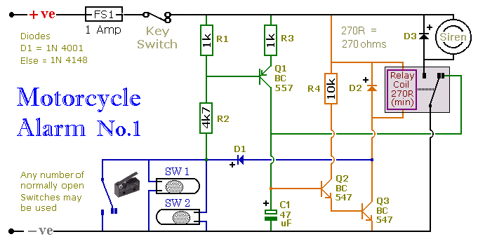
A Transistor Based Motorcycle Alarm circuit
This circuit includes a timed output and an automatic reset feature. It can be manually operated using a key switch or a concealed switch. By incorporating an external relay, the circuit will automatically engage or immobilize the machine each time...
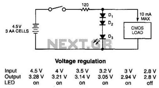
Diode Cmos Stabilizer
The simple diode network can stabilize the voltage supplied to CMOS circuitry from a battery. D1 and D2 must have a combined forward-voltage drop of about 1.5 V. D3 is an LED with a forward-voltage drop of about 1.7 V....
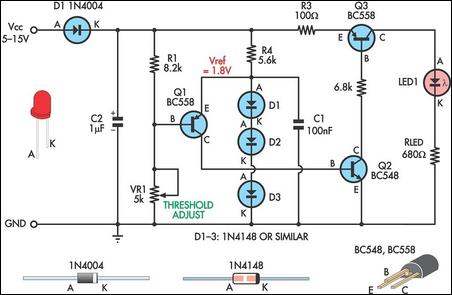
Low Supply Rail Detection
This is a simple low supply rail detection circuit that is inexpensive and can be assembled in approximately 20 minutes. Its low power consumption makes it suitable for integration into battery-powered devices. Instead of utilizing an operational amplifier, the circuit...

rising pitch siren
A two-transistor electronic siren breadboard circuit that produces an audible rising pitch on a loudspeaker. This circuit serves as a tutorial for beginners in electronics.
The two-transistor siren circuit operates by utilizing the properties of transistors to create an oscillating signal...
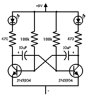
Transistor LED flasher
The circuits discussed here are simple LED flashers that typically illuminate one or two LEDs, contrasting with more complex light chaser circuits that can flash four or more. While the most basic option is a flashing LED, it lacks control...
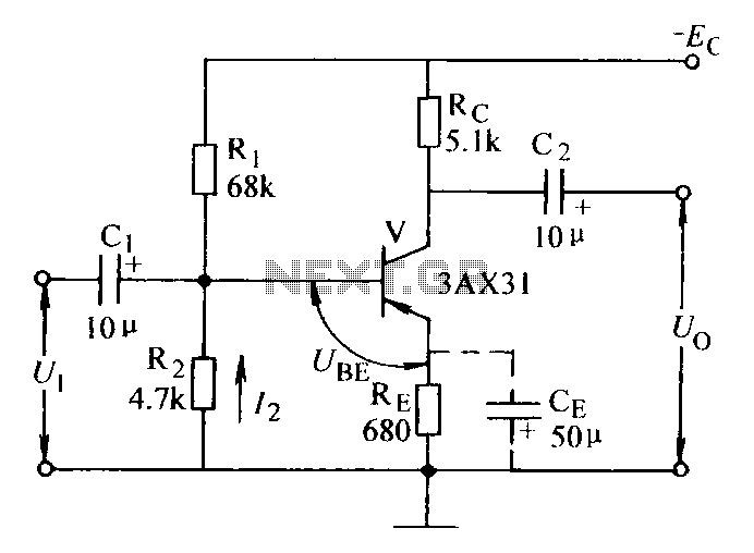
Current negative feedback voltage divider biasing circuit diagram
Current negative feedback voltage divider biased circuit diagram.
The current negative feedback voltage divider biased circuit is a configuration commonly used in electronic amplifiers to stabilize the operating point and improve linearity. This circuit typically consists of an amplifier, a voltage...
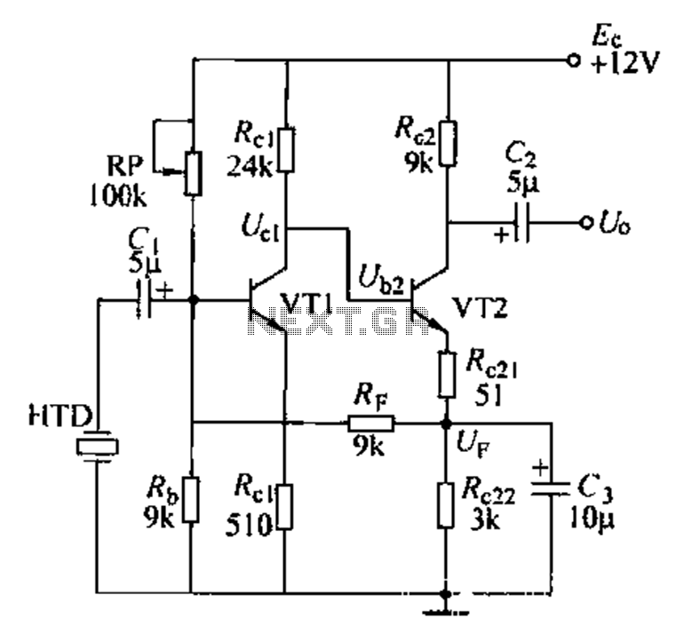
Voice amplifier transistor
Dctl is a two-stage amplifier, with the first stage amplifying the collector voltage of transistor VT1. The second stage, represented by VT2, is proportional to the current flowing through the winding. The RF signal is applied to the sub-base of...
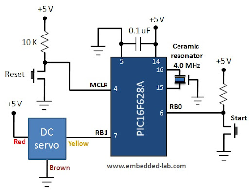
Servo motor control
A servo motor is a specialized geared DC motor that includes an electronic circuit for controlling the direction and position of the motor shaft. Due to its capability for precise angular positioning, servo motors are widely utilized in robotics, as...
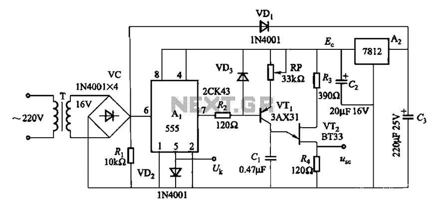
From power fluctuations of one single-junction transistor trigger circuit
Both circuits can synchronize trapezoidal wave voltage, which is converted into intermittent small rectangular pulses. Its working principle involves periodic operation in synchronization with the grid frequency of the zero-volt switching voltage of the DC chopper. Due to the low...