


3.3V and 5V DC DC converter circuit design using LT3692 DC converter dual tracking regulator
#DC-DC converter
#LT3692
#power supply
#3.3V
#5V
#dual tracking regulator
#PWM
#step-down converter
#automotive
#distributed supply
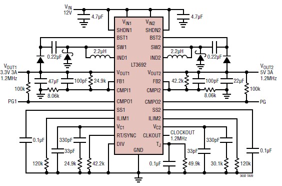
Description: The LT3692 dual current mode PWM step-down DC-DC converter circuit, featuring two internal 3.5A switches, can be designed into a simple power supply circuit suitable for various electronic applications, such as distributed supply regulation or automotive circuits. The LT3692 provides independent input voltage, shutdown, feedback, soft-start, current limit, and comparator pins for each channel. To enhance efficiency and reduce component size, both converters have a programmable maximum current limit and can be synchronized to a common external clock input or a resistor-settable fixed frequency ranging from 250kHz to 2.25MHz using the internal oscillator. A frequency divider is included for channel 1 to optimize component size further. Throughout all frequencies, a 180° phase relationship between channels is maintained, which minimizes voltage ripple and component size. A clock output is available for synchronizing multiple regulators. The presented DC-DC converter circuit will provide two independent output voltages of 3.3V and 5V, with a maximum output current of approximately 3A for each channel. This schematic circuit requires only a few external electronic components and is powered by a 12V DC power supply. Key features of this DC-DC converter include independent synchronized switching frequencies, antiphase switching, flexible output voltage tracking, enhanced short-circuit protection, a low dropout of 95% maximum duty cycle, and a low shutdown current of less than 10µA.
The LT3692 is an advanced solution for applications requiring efficient power conversion with minimal component count. This dual-channel DC-DC converter is designed to operate in a variety of environments, making it suitable for both consumer electronics and automotive applications. The independent input voltage feature allows for versatility in power sourcing, enabling the converter to adapt to different voltage levels as needed.
The programmable maximum current limit is a critical feature that allows designers to set the output current to match the specific requirements of the load, thereby preventing overcurrent conditions that could damage the circuit. The synchronization capability, whether through an external clock or an internal oscillator, ensures that multiple converters can operate in harmony, reducing electromagnetic interference and enhancing overall system performance.
The 180° phase relationship between the two channels is particularly beneficial in applications where minimizing output voltage ripple is essential. This design choice allows for smoother operation and improved transient response, which is crucial in applications where load conditions may change rapidly.
The output voltage tracking feature provides flexibility in applications where the output voltage needs to be adjusted dynamically based on the load or system requirements. This capability is particularly useful in battery management systems and other power-sensitive applications.
The enhanced short-circuit protection ensures that the converter can withstand fault conditions without sustaining damage, thereby increasing the reliability of the overall system. The low dropout capability allows for efficient operation even when the input voltage is close to the output voltage, maximizing the utility of the available power supply.
Finally, the low shutdown current is advantageous for battery-powered applications, as it helps extend battery life by minimizing power consumption during idle periods. Overall, the LT3692 dual current mode PWM step-down DC-DC converter represents a robust and flexible solution for a wide range of electronic power supply needs.Using the LT3692 dual current mode PWM step-down DC DC converter circuit with two internal 3. 5A switches can be designed a very simple power supply circuit, that can be used for various electronic circuits applications like : distributed supply regulations or automotive circuits. LT3692 provide independent input voltage, shutdown, feedback, soft -start, current limit and comparator pins for each channel. To optimize efficiency and component size, both converters have a programmable maximum current limit and are synchronized to either a common external clock input, or a resistor settable fixed 250kHz to 2. 25MHz internal oscillator. A frequency divider is provided for channel 1 to further optimize component size. At all frequencies, a 180 ° phase relationship between channels is maintained, reducing voltage ripple and component size.
A clock output is available for synchronizing multiple regulators. This DC DC converter circuit presented in this schematic diagram, will provide two independent voltages :3. 3 volts and 5 volt. The maximum output current that can be provided by this DC DC converter electronic project is around 3A for each channel.
As you can see in this schematic circuit, this project require few external electronic parts and needs to be powered from a 12 volt DC power supply. Some features of this DC DC converter electronic project are : independent synchronized switching frequencies, antiphase switching, flexible output voltage tracking, enhanced short-circuit protection, low dropout: 95% maximum duty cycle, low shutdown current: <10 A.
The LT3692 is an advanced solution for applications requiring efficient power conversion with minimal component count. This dual-channel DC-DC converter is designed to operate in a variety of environments, making it suitable for both consumer electronics and automotive applications. The independent input voltage feature allows for versatility in power sourcing, enabling the converter to adapt to different voltage levels as needed.
The programmable maximum current limit is a critical feature that allows designers to set the output current to match the specific requirements of the load, thereby preventing overcurrent conditions that could damage the circuit. The synchronization capability, whether through an external clock or an internal oscillator, ensures that multiple converters can operate in harmony, reducing electromagnetic interference and enhancing overall system performance.
The 180° phase relationship between the two channels is particularly beneficial in applications where minimizing output voltage ripple is essential. This design choice allows for smoother operation and improved transient response, which is crucial in applications where load conditions may change rapidly.
The output voltage tracking feature provides flexibility in applications where the output voltage needs to be adjusted dynamically based on the load or system requirements. This capability is particularly useful in battery management systems and other power-sensitive applications.
The enhanced short-circuit protection ensures that the converter can withstand fault conditions without sustaining damage, thereby increasing the reliability of the overall system. The low dropout capability allows for efficient operation even when the input voltage is close to the output voltage, maximizing the utility of the available power supply.
Finally, the low shutdown current is advantageous for battery-powered applications, as it helps extend battery life by minimizing power consumption during idle periods. Overall, the LT3692 dual current mode PWM step-down DC-DC converter represents a robust and flexible solution for a wide range of electronic power supply needs.Using the LT3692 dual current mode PWM step-down DC DC converter circuit with two internal 3. 5A switches can be designed a very simple power supply circuit, that can be used for various electronic circuits applications like : distributed supply regulations or automotive circuits. LT3692 provide independent input voltage, shutdown, feedback, soft -start, current limit and comparator pins for each channel. To optimize efficiency and component size, both converters have a programmable maximum current limit and are synchronized to either a common external clock input, or a resistor settable fixed 250kHz to 2. 25MHz internal oscillator. A frequency divider is provided for channel 1 to further optimize component size. At all frequencies, a 180 ° phase relationship between channels is maintained, reducing voltage ripple and component size.
A clock output is available for synchronizing multiple regulators. This DC DC converter circuit presented in this schematic diagram, will provide two independent voltages :3. 3 volts and 5 volt. The maximum output current that can be provided by this DC DC converter electronic project is around 3A for each channel.
As you can see in this schematic circuit, this project require few external electronic parts and needs to be powered from a 12 volt DC power supply. Some features of this DC DC converter electronic project are : independent synchronized switching frequencies, antiphase switching, flexible output voltage tracking, enhanced short-circuit protection, low dropout: 95% maximum duty cycle, low shutdown current: <10 A.
Isolated-dc-dc-converter
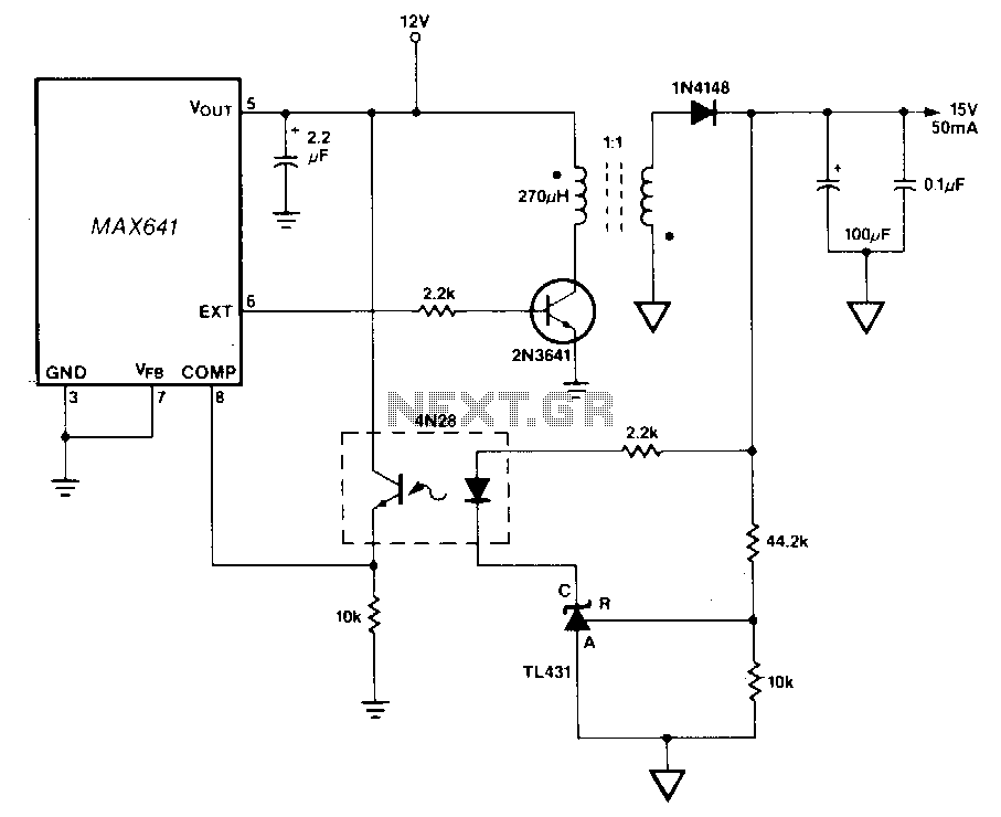
In this circuit, a TU31 shunt regulator is utilized to monitor the output voltage. The TU31 activates the LED of a 4N28 optocoupler, which delivers feedback to the MAX641 while ensuring isolation between the input voltage of +12 V and...
DC Motor Speed Controller
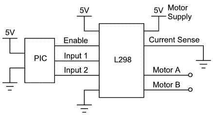
This article demonstrates how to control a DC motor using an H-bridge driver chip with PWM output from a PIC microcontroller for speed control. While a PIC microcontroller is utilized, other controllers such as AVRs, Basic Stamps, and certain Picaxe...
Motor speed controller with timer 555
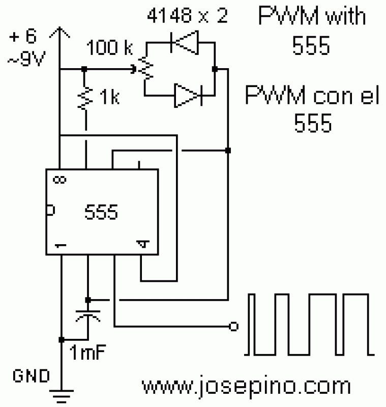
Pulse width modulation (PWM) is a technique to control analog circuits with a digital output. PWM is used in many applications, especially to control light intensity and speed on motors. A PWM circuit makes a square wave with a variable...
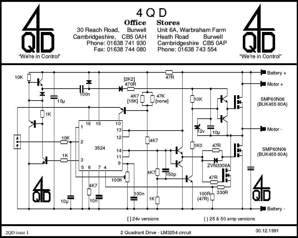
pwm 01
A commercial motor controller is more than just a circuit designed to adjust the speed of a motor. It encompasses various features that enhance its functionality, which are explained in a guided overview. To effectively control the speed of a...

Eng Sony AV 3400
The original power supply AC-3400 features a charger function. In addition to the power button and the indicator light for power status, the front panel includes a charge level indicator for the accumulator, a start button, and a socket for...
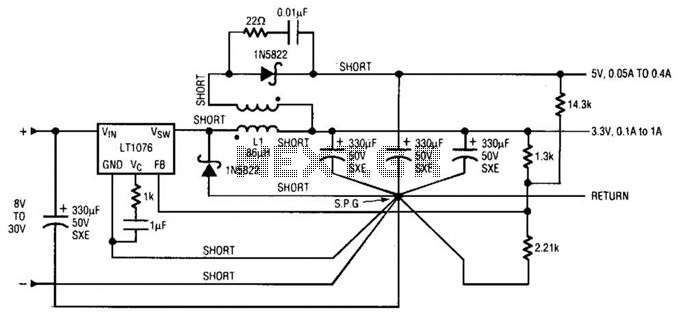
Dc-Dc Converter Circuit With 3.3V And 5V Outputs Circuit
Input voltages can range from 8 V to 30 V. The load range for the 5 V output is from 0.05 A to 5 A, while the load range for the 3.3 V output is from 0.1 A to 1...
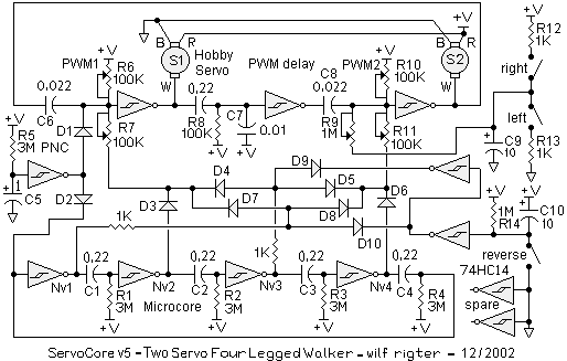
Servocore 2-motor walker circuit
There is an advantage in using continuously active PWM signals. The main reason is that the asynchronous frequencies of the PWM core and microcore can sometimes result in a shortened PWM pulse. The servo recognizes this as a command for...
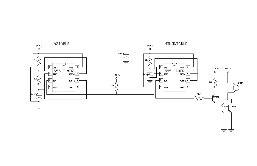
pulse width modulated (PWM) controller for high current
The second 555 timer was configured as a monostable circuit, commonly referred to as a one-shot since an output pulse only occurs if there is a trigger on the input. When this timer is triggered, the potentiometer in the RC...
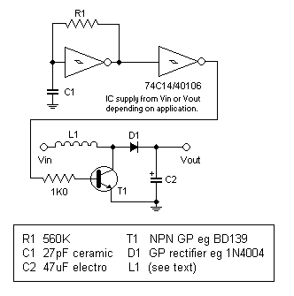
DC-DC converter to step up input voltage
This circuit is a simple design that outputs a voltage higher than the input. It can be used to power 12V or 9V devices from a 6V system or to operate 6V devices from a 1.5V battery. The circuit utilizes...