


33v and 5v dual tracking regulator using lt3692 dc converter
#LT3692
#DC-DC converter
#dual tracking regulator
#3.3V
#5V
#PWM
#step-down
#power supply
#automotive circuits
#distributed supply
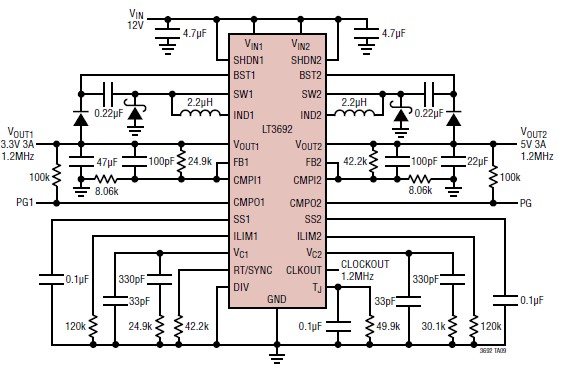
Description: The LT3692 dual current mode PWM step-down DC-DC converter circuit, featuring two internal 3.5A switches, can be utilized to design a straightforward power supply circuit suitable for various electronic applications, including distributed supply regulations and automotive circuits. The LT3692 offers independent input voltage, shutdown, feedback, soft-start, current limit, and comparator pins for each channel. To enhance efficiency and minimize component size, both converters allow for a programmable maximum current limit and can be synchronized to either a common external clock input or a resistor-settable fixed frequency ranging from 250kHz to 2.25MHz using an internal oscillator. A frequency divider is available for channel 1 to further optimize component size. Throughout all frequencies, a 180° phase relationship between channels is maintained, which reduces voltage ripple and component size. Additionally, a clock output is provided for synchronizing multiple regulators. This DC-DC converter circuit, as depicted in the schematic diagram, will deliver two independent voltages: 3.3 volts and 5 volts. The maximum output current that this DC-DC converter electronic project can provide is approximately 3A for each channel. The schematic circuit requires only a few external electronic components and must be powered by a 12-volt DC power supply. Key features of this DC-DC converter electronic project include independent synchronized switching frequencies, antiphase switching, flexible output voltage tracking, enhanced short-circuit protection, a low dropout rate with a maximum duty cycle of 95%, and a low shutdown current of less than 10µA.
The LT3692 is designed to facilitate the creation of efficient and compact power supply solutions in various applications. Each channel of the converter operates independently, allowing for flexible voltage outputs tailored to specific needs. The programmable maximum current limit feature is particularly advantageous in preventing overload conditions, ensuring reliability in demanding environments.
The synchronization capabilities of the LT3692 enable multiple converters to operate in unison, which is critical in applications where maintaining a consistent power supply is essential. The internal oscillator's frequency can be adjusted to optimize performance for specific load conditions while minimizing electromagnetic interference (EMI), a common concern in automotive and distributed systems.
The antiphase switching characteristic is a notable design feature, as it effectively cancels out voltage ripple, leading to improved output stability. This is particularly beneficial in sensitive electronic applications where voltage fluctuations can lead to performance degradation or malfunction.
The inclusion of enhanced short-circuit protection ensures that the circuit can withstand fault conditions without sustaining damage, which is crucial for maintaining long-term reliability. The low dropout operation, allowing a maximum duty cycle of 95%, enhances efficiency, particularly in battery-powered applications, where conserving energy is paramount.
In summary, the LT3692 dual current mode PWM step-down DC-DC converter circuit is a versatile and robust solution for generating multiple output voltages with high efficiency and reliability, making it suitable for a wide range of electronic applications.Using the LT3692 dual current mode PWM step-down DC DC converter circuit with two internal 3. 5A switches can be designed a very simple power supply circuit, that can be used for various electronic circuits applications like : distributed supply regulations or automotive circuits. LT3692 provide independent input voltage, shutdown, feedback, soft -start, current limit and comparator pins for each channel. To optimize efficiency and component size, both converters have a programmable maximum current limit and are synchronized to either a common external clock input, or a resistor settable fixed 250kHz to 2. 25MHz internal oscillator. A frequency divider is provided for channel 1 to further optimize component size. At all frequencies, a 180 ° phase relationship between channels is maintained, reducing voltage ripple and component size.
A clock output is available for synchronizing multiple regulators. This DC DC converter circuit presented in this schematic diagram, will provide two independent voltages :3. 3 volts and 5 volt. The maximum output current that can be provided by this DC DC converter electronic project is around 3A for each channel.
As you can see in this schematic circuit, this project require few external electronic parts and needs to be powered from a 12 volt DC power supply. Some features of this DC DC converter electronic project are : independent synchronized switching frequencies, antiphase switching, flexible output voltage tracking, enhanced short-circuit protection, low dropout: 95% maximum duty cycle, low shutdown current: <10 A.
The LT3692 is designed to facilitate the creation of efficient and compact power supply solutions in various applications. Each channel of the converter operates independently, allowing for flexible voltage outputs tailored to specific needs. The programmable maximum current limit feature is particularly advantageous in preventing overload conditions, ensuring reliability in demanding environments.
The synchronization capabilities of the LT3692 enable multiple converters to operate in unison, which is critical in applications where maintaining a consistent power supply is essential. The internal oscillator's frequency can be adjusted to optimize performance for specific load conditions while minimizing electromagnetic interference (EMI), a common concern in automotive and distributed systems.
The antiphase switching characteristic is a notable design feature, as it effectively cancels out voltage ripple, leading to improved output stability. This is particularly beneficial in sensitive electronic applications where voltage fluctuations can lead to performance degradation or malfunction.
The inclusion of enhanced short-circuit protection ensures that the circuit can withstand fault conditions without sustaining damage, which is crucial for maintaining long-term reliability. The low dropout operation, allowing a maximum duty cycle of 95%, enhances efficiency, particularly in battery-powered applications, where conserving energy is paramount.
In summary, the LT3692 dual current mode PWM step-down DC-DC converter circuit is a versatile and robust solution for generating multiple output voltages with high efficiency and reliability, making it suitable for a wide range of electronic applications.Using the LT3692 dual current mode PWM step-down DC DC converter circuit with two internal 3. 5A switches can be designed a very simple power supply circuit, that can be used for various electronic circuits applications like : distributed supply regulations or automotive circuits. LT3692 provide independent input voltage, shutdown, feedback, soft -start, current limit and comparator pins for each channel. To optimize efficiency and component size, both converters have a programmable maximum current limit and are synchronized to either a common external clock input, or a resistor settable fixed 250kHz to 2. 25MHz internal oscillator. A frequency divider is provided for channel 1 to further optimize component size. At all frequencies, a 180 ° phase relationship between channels is maintained, reducing voltage ripple and component size.
A clock output is available for synchronizing multiple regulators. This DC DC converter circuit presented in this schematic diagram, will provide two independent voltages :3. 3 volts and 5 volt. The maximum output current that can be provided by this DC DC converter electronic project is around 3A for each channel.
As you can see in this schematic circuit, this project require few external electronic parts and needs to be powered from a 12 volt DC power supply. Some features of this DC DC converter electronic project are : independent synchronized switching frequencies, antiphase switching, flexible output voltage tracking, enhanced short-circuit protection, low dropout: 95% maximum duty cycle, low shutdown current: <10 A.
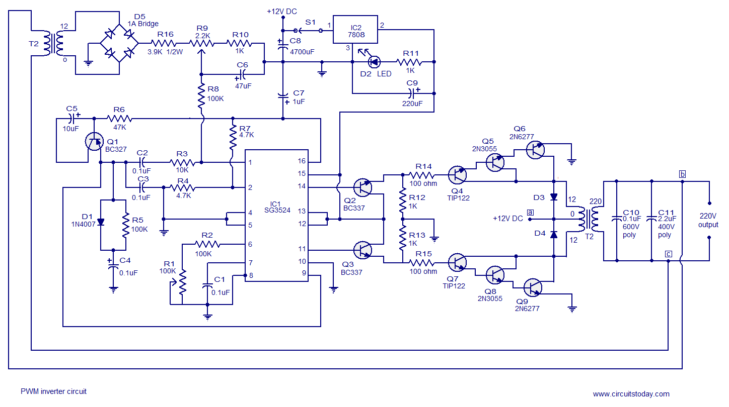
PWM inverter circuit based on SG3524 : 12V input 220V output 250W
A simple PWM inverter circuit utilizes the SG3524 integrated circuit. This PWM inverter is designed for a 12V input, providing a 220V output with a maximum output power of 250 watts. The output power can be extended further.
The described PWM...
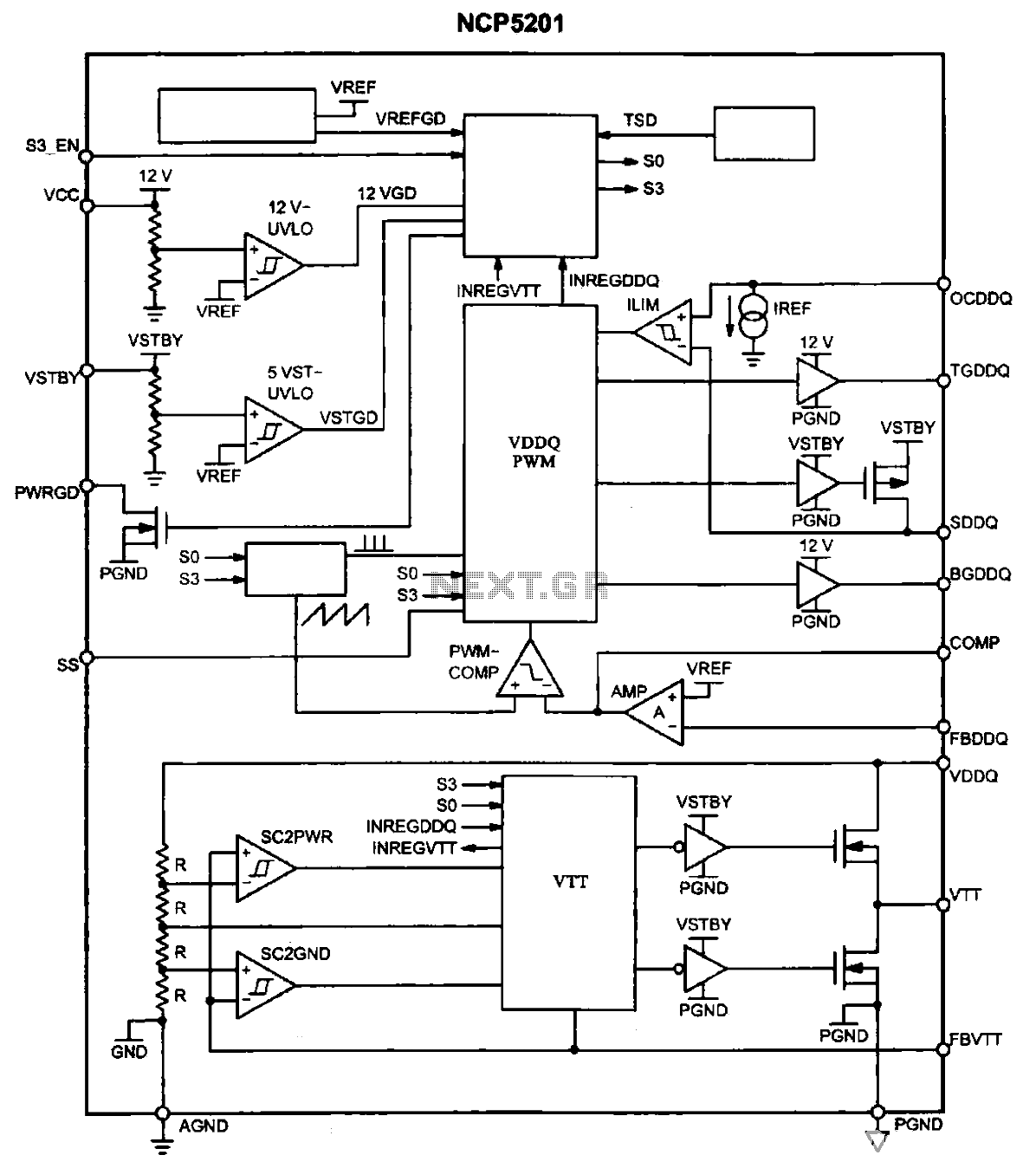
Internal functional block diagram of NCP5201
The NCP5201 chip contains two sets of PWM signal generating circuits, each with a dedicated set of output pins. These circuits produce two opposite phase PWM signals, which are applied to the gates of three field effect transistors. This arrangement...
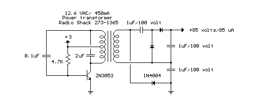
12V DC to 85V DC Converter
The circuit below is a DC to DC converter using a standard 12 VAC center tapped power transformer wired as a blocking oscillator. The circuit is not very efficient but will produce a high voltage usable for low power applications....
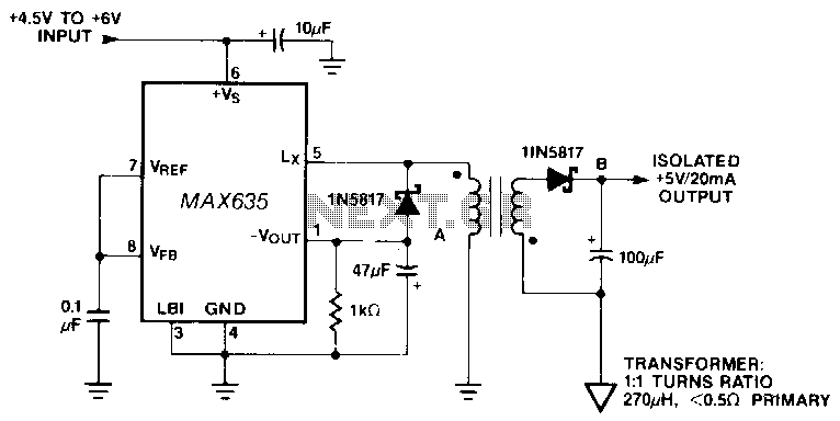
Lsolated-converter
In this circuit, a negative output voltage DC-DC converter generates a -5 V output at pin A. To achieve -5 V at point A, the primary of the transformer must fly back to a diode drop that is more negative...
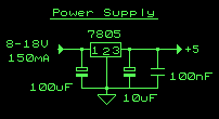
Simple 5V power supply for digital circuits
This circuit is a small +5V power supply, which is useful when experimenting with digital electronics. Small inexpensive wall transformers with variable output voltage are available from any electronics shop and supermarket. Those transformers are easily available, but usually their...
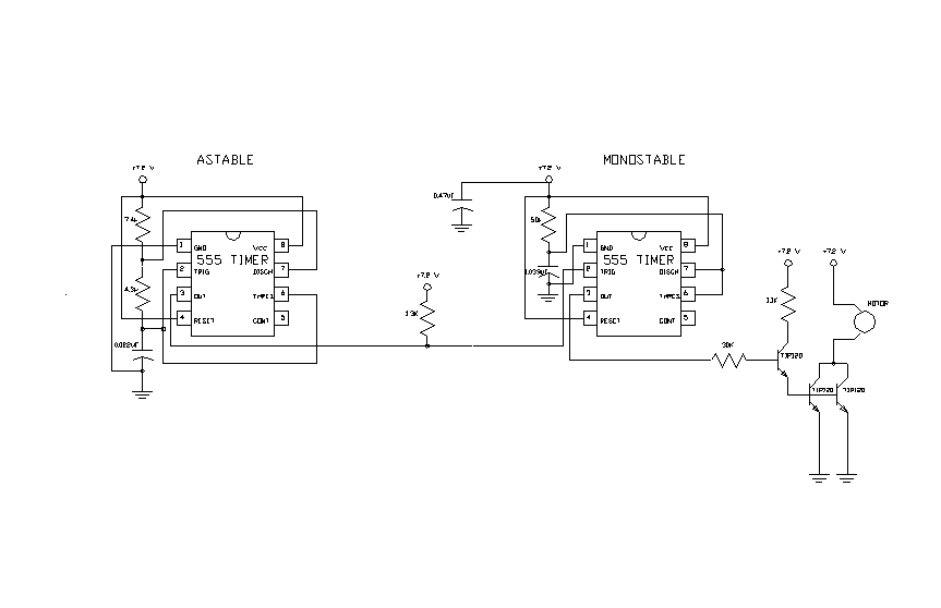
pulse width modulated (PWM) controller for high current
The second 555 timer was configured as a monostable circuit, commonly referred to as a one-shot since an output pulse only occurs if there is a trigger on the input. When this timer is triggered, the potentiometer in the RC...
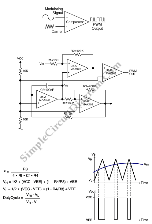
PWM Modulator Using Op-Amp
This is a simple PWM modulator circuit. Comparing the message signal to a ramp or triangular waveform is the simplest way to produce a PWM signal. When the...
The PWM (Pulse Width Modulation) modulator circuit operates by comparing a modulating signal,...
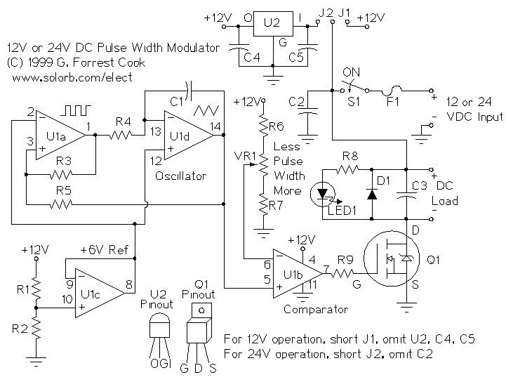
LM324N PWM Motor Speed Controller
PWM is a device that can be utilized as an efficient light dimmer or DC motor speed controller. Function: for a general-purpose device that can...
PWM (Pulse Width Modulation) is a versatile technique widely employed in various electronic applications, particularly for...

Can produce circuits within the range of 1-99% duty cycle of the digital set-precision PWM wave
The circuit described is a crystal oscillation circuit using a CM OS inverting configuration, designed to ensure accurate operation. It employs a BCD counter (IC2) capable of achieving a maximum oscillation frequency of 2 MHz, which is 100 times the...