


DC generator automatic voltage regulator circuit
#DC generator
#automatic voltage regulator
#voltage regulation
#shunt machine
#40kW
#230V
#voltage change rate
#power regulation
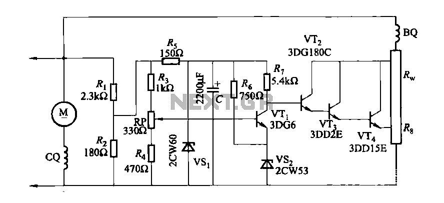
Description: The DC generator automatic voltage regulator circuit is illustrated in Figure 7-53. This circuit is designed for a 40kW, 230V DC shunt complex machine, with a voltage change rate of up to 2.5 percent. In Figure 7-53, BQ represents the shunt winding, while co represents the series winding in conjunction with the external shunt resistor Rw in the winding circuit. The adjustment potentiometer RP allows for modification of the generator output voltage setpoint.
The DC generator automatic voltage regulator circuit is a critical component in maintaining stable output voltage in a 40kW, 230V DC shunt complex machine. The circuit operates by monitoring the output voltage and making necessary adjustments to ensure that it remains within specified limits, with a voltage change rate of no more than 2.5 percent.
In the schematic, the shunt winding (BQ) is connected to the generator's output terminals, which allows it to sense the voltage level. The series winding (co) is incorporated into the circuit along with an external shunt resistor (Rw), which is essential for controlling the overall voltage feedback loop. The presence of the series winding aids in improving the response time of the voltage regulation, especially during load variations.
The adjustment potentiometer (RP) plays an important role in the regulation process. By varying the resistance through this potentiometer, the operator can set the desired output voltage level. This capability is particularly useful during initial setup or when the load conditions change significantly, allowing for fine-tuning of the generator's performance.
Overall, this automatic voltage regulator circuit is an essential feature for ensuring the reliable operation of the DC generator, providing both stability and flexibility in voltage management for various applications.DC generator automatic voltage regulator circuit is shown in Figure 7-53. This circuit is used to 40kW, 230V DC shunt complex machine, the voltage change rate up to 2.5 percent . In Figure 7-53, BQ for the shunt winding, co} for the series winding in series with the external shunt resistor Rw winding circuit. Adjustment potentiometer RP, can change the generator output voltage setpoint.
The DC generator automatic voltage regulator circuit is a critical component in maintaining stable output voltage in a 40kW, 230V DC shunt complex machine. The circuit operates by monitoring the output voltage and making necessary adjustments to ensure that it remains within specified limits, with a voltage change rate of no more than 2.5 percent.
In the schematic, the shunt winding (BQ) is connected to the generator's output terminals, which allows it to sense the voltage level. The series winding (co) is incorporated into the circuit along with an external shunt resistor (Rw), which is essential for controlling the overall voltage feedback loop. The presence of the series winding aids in improving the response time of the voltage regulation, especially during load variations.
The adjustment potentiometer (RP) plays an important role in the regulation process. By varying the resistance through this potentiometer, the operator can set the desired output voltage level. This capability is particularly useful during initial setup or when the load conditions change significantly, allowing for fine-tuning of the generator's performance.
Overall, this automatic voltage regulator circuit is an essential feature for ensuring the reliable operation of the DC generator, providing both stability and flexibility in voltage management for various applications.DC generator automatic voltage regulator circuit is shown in Figure 7-53. This circuit is used to 40kW, 230V DC shunt complex machine, the voltage change rate up to 2.5 percent . In Figure 7-53, BQ for the shunt winding, co} for the series winding in series with the external shunt resistor Rw winding circuit. Adjustment potentiometer RP, can change the generator output voltage setpoint.
power supply design
The more one understands about any subject, the more interesting it becomes. As this article is read, it will be found that the subject of...
A comprehensive electronic schematic typically involves various components, each serving a specific function in the overall...
Voltage regulator for projection lamp
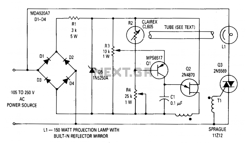
The circuit regulates the RMS output voltage across a load, specifically a projection lamp, to 100 volts ±2% for input voltages ranging from 105 to 250 volts AC. This regulation is achieved by indirectly sensing the light output of lamp...
0-30 VDC Stabilized Power Supply with Current Control 0.002-3 A
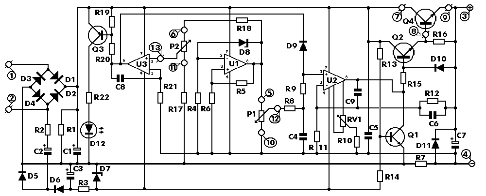
The circuit begins with a step-down mains transformer featuring a secondary winding rated at 24 V/3 A, which connects across the input points at pins 1 and 2. The quality of the output supply is directly related to the transformer's...
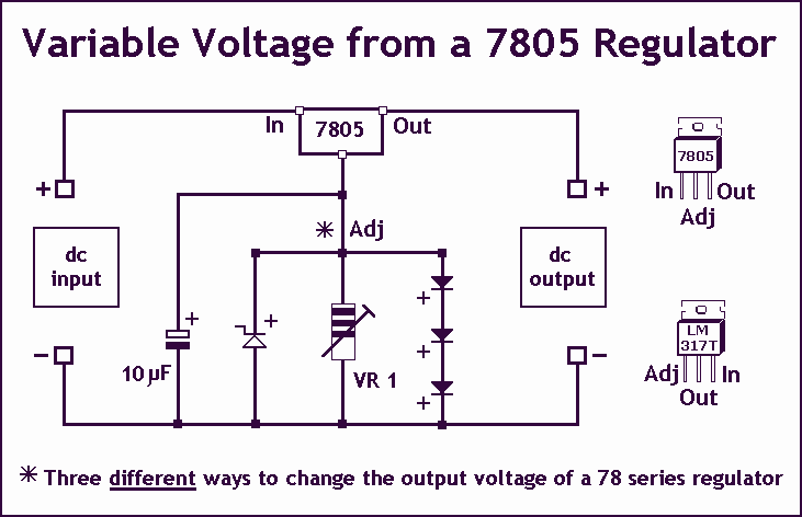
Variable Voltage Regulation
Controlling the output voltage from a regulator can be made variable in three ways:
1. Using a fixed reference zener diode to increase the output by the value of the zener
2. A variable resistor for variable output, note that...
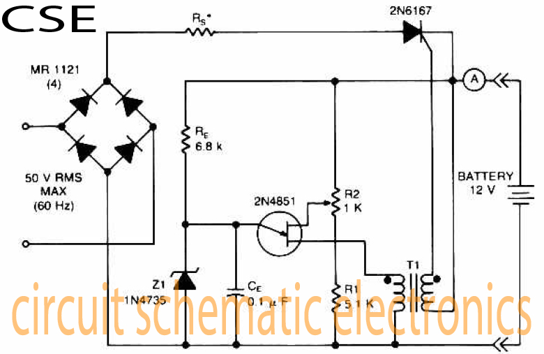
Variable charger circuit Schematic Diagram
The accumulator charger circuit must provide a voltage that matches the specifications of the batteries being charged. For a 12-volt accumulator, the output voltage should not exceed 12 volts, nor should it fall significantly below this threshold. Failure to maintain...
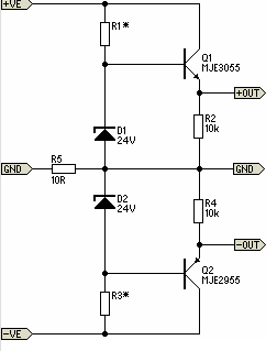
Simple Pre-Regulator
There will be many occasions when it is beneficial to utilize the P05 supply module sourced from a higher voltage supply. For instance, this could be advantageous when integrating balanced inputs.
The P05 supply module is designed to facilitate the conversion...
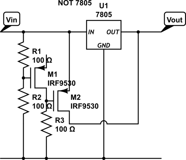
power Voltage supply clipping to <=3.3V
Supply it with a Li-Ion cell, which has a voltage range of 2.7 to 4.2V. The complexity of a buck/boost converter is not desired. While it is possible to regulate the voltage down to anything below 2.5V, it would be...
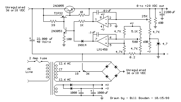
Variable Voltage and Current Power Supply circuit
An alternative approach to utilizing operational amplifiers (op-amps) for power supply regulation is presented. This method necessitates an additional winding on the power transformer to provide the op-amps with a bipolar voltage of +/- 8 volts. The negative voltage generated...
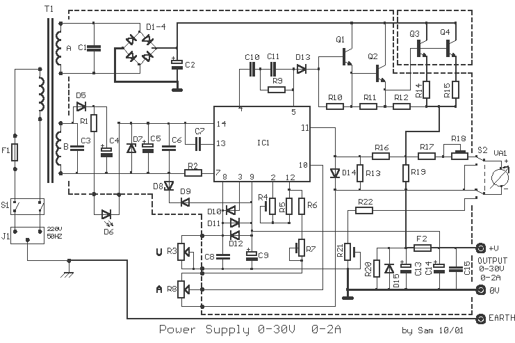
Power Supply 0-30V / 0-2A
The basic requirements for a laboratory power supply are to provide the necessary voltages and currents with low output resistance, low noise, minimal ripple, and good stabilization. These requirements are addressed within the circuit design. Many power supplies incorporate electronic...