


Dual-tracking-regulator
#dual-tracking
#voltage regulator
#MAX634
#MAX630
#inverting regulator
#battery power
#±15V output
#12V battery
#reference voltage
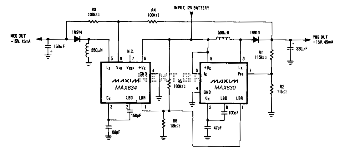
Description: A MAX634 inverting regulator is combined with a MAX630 to provide a dual tracking ±15 V output from a 12-V battery. The reference for the -15 V output is derived from the positive output via resistors R3 and R4. Both regulators are configured to optimize output power at low battery voltages by lowering the oscillator frequency through the LBR when the battery voltage drops to 8.5 V.
The circuit employs a MAX634 inverting regulator, which is designed to produce a negative output voltage. In this configuration, it works in conjunction with a MAX630 positive voltage regulator to generate a dual output of ±15 V. The positive output voltage is derived directly from the 12-V battery source, while the -15 V output is obtained through a feedback mechanism that utilizes resistors R3 and R4. These resistors form a voltage divider that provides a stable reference voltage for the inverting regulator, ensuring that the negative output remains consistent and tracks the positive output accurately.
To enhance performance, both regulators are equipped with a feature that allows them to adapt to low battery conditions. Specifically, when the battery voltage falls to 8.5 V, the regulators reduce their oscillator frequency via the LBR (Low Battery Regulation) pin. This adjustment helps to maintain adequate output power levels even when the input voltage is low, thereby extending the operational life of the circuit under suboptimal conditions. The design focuses on efficiency and stability, making it suitable for applications where reliable dual voltage outputs are necessary, especially in battery-powered systems.A MAX634 inverting regulator is combined with a MAX630 to provide a dual tracking ±15 output from a 12-V battery. The reference for the -15 V output is derived from the positive output via R3 and R4. Both regulators are set to maximize output power at low battery voltages by reducing the oscillator frequency, via LBR, when "BATT falls to 8.5 V.
The circuit employs a MAX634 inverting regulator, which is designed to produce a negative output voltage. In this configuration, it works in conjunction with a MAX630 positive voltage regulator to generate a dual output of ±15 V. The positive output voltage is derived directly from the 12-V battery source, while the -15 V output is obtained through a feedback mechanism that utilizes resistors R3 and R4. These resistors form a voltage divider that provides a stable reference voltage for the inverting regulator, ensuring that the negative output remains consistent and tracks the positive output accurately.
To enhance performance, both regulators are equipped with a feature that allows them to adapt to low battery conditions. Specifically, when the battery voltage falls to 8.5 V, the regulators reduce their oscillator frequency via the LBR (Low Battery Regulation) pin. This adjustment helps to maintain adequate output power levels even when the input voltage is low, thereby extending the operational life of the circuit under suboptimal conditions. The design focuses on efficiency and stability, making it suitable for applications where reliable dual voltage outputs are necessary, especially in battery-powered systems.A MAX634 inverting regulator is combined with a MAX630 to provide a dual tracking ±15 output from a 12-V battery. The reference for the -15 V output is derived from the positive output via R3 and R4. Both regulators are set to maximize output power at low battery voltages by reducing the oscillator frequency, via LBR, when "BATT falls to 8.5 V.
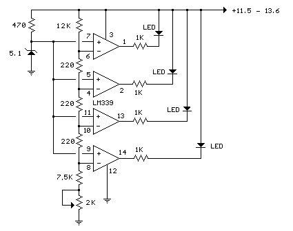
12V Battery Meter with 4 LEDs
In the circuit below, a quad voltage comparator (LM339) is used as a simple bar graph meter to indicate the charge condition of a 12 volt, lead acid battery. A 5 volt reference voltage is connected to each of the...
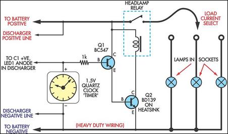
High-Current Battery Discharger
If you have a diverse assortment of 12V batteries in different conditions, this straightforward circuit will enable you to easily assess their capacity.
This circuit is designed to evaluate the capacity of 12V batteries, which may be in varying states...
fireworks controller circuit
A 12V battery pack from a PowerWheels car is used alongside two wooden planks with several nails driven through them. Each nail is wrapped with speaker wire that connects to ignitors, while the other end returns to a central positive...
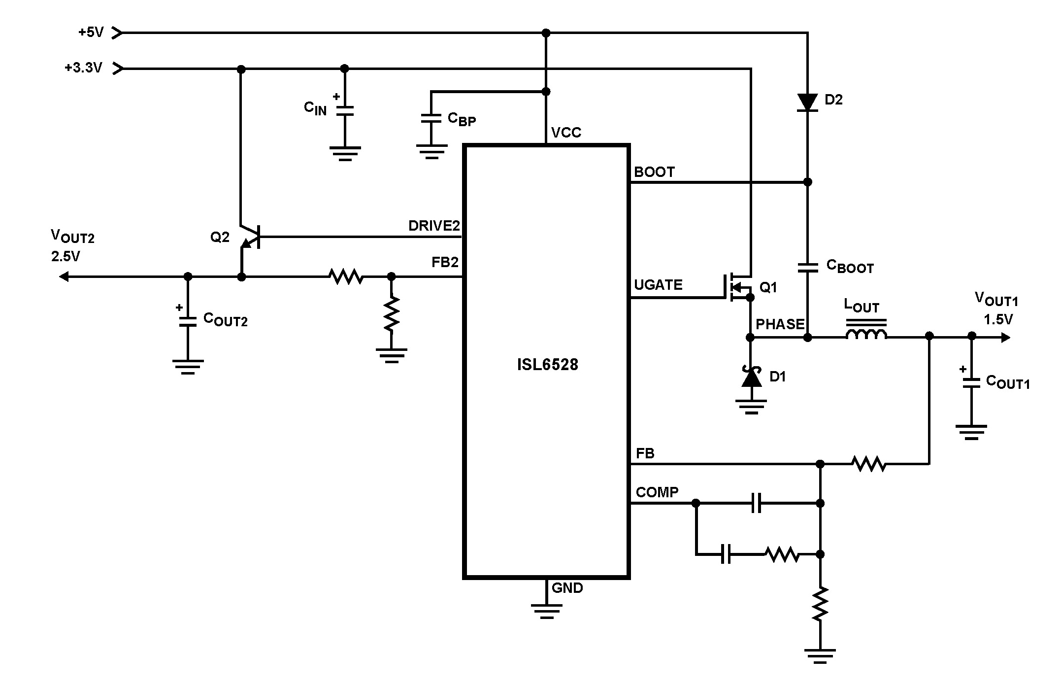
ISL6528 Dual Regulator-Standard Buck PWM and Linear Power Controller
The ISL6528 offers power control and protection for two output voltages in high-performance graphics cards and other embedded processor applications. This dual-output controller drives an N-Channel MOSFET in a standard buck topology and an NPN pass transistor in a linear...
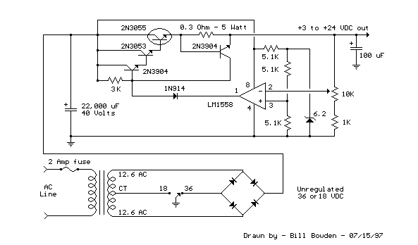
Variable 3 - 24 Volt / 3 Amp Power Supply circuit
This regulated power supply can be adjusted from 3 to 25 volts and is current limited to 2 amps as shown, but may be increased to 3 amps or more by selecting a smaller current sense resistor (0.3 ohm). The...
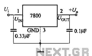
Three-terminal voltage regulator integrated fixed a typical wiring circuit
A fixed three-terminal integrated voltage regulator can be directly employed in various electronic devices as a voltage regulator. It features internal protections such as overcurrent protection, thermal protection, and safe operating area protection, making the circuit easy to use, safe,...
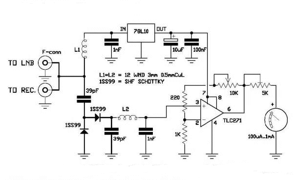
DIY Satellite Finder Circuit
A circuit has been identified that integrates a voltage regulator and filter to isolate the voltage supplied by the receiver for powering an operational amplifier (op-amp) that drives a meter. Additionally, the circuit isolates the carrier frequency from the satellite,...
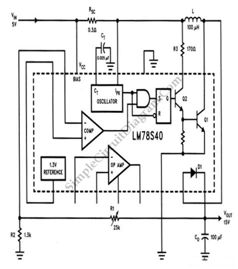
LM78S40 5V to 15V Step-up Voltage Regulator
A step-up conversion can be achieved without utilizing a transformer. This circuit is capable of converting a 5V DC source into 15V. It is important to note that there is no power gain.
The described circuit employs a DC-DC boost converter...
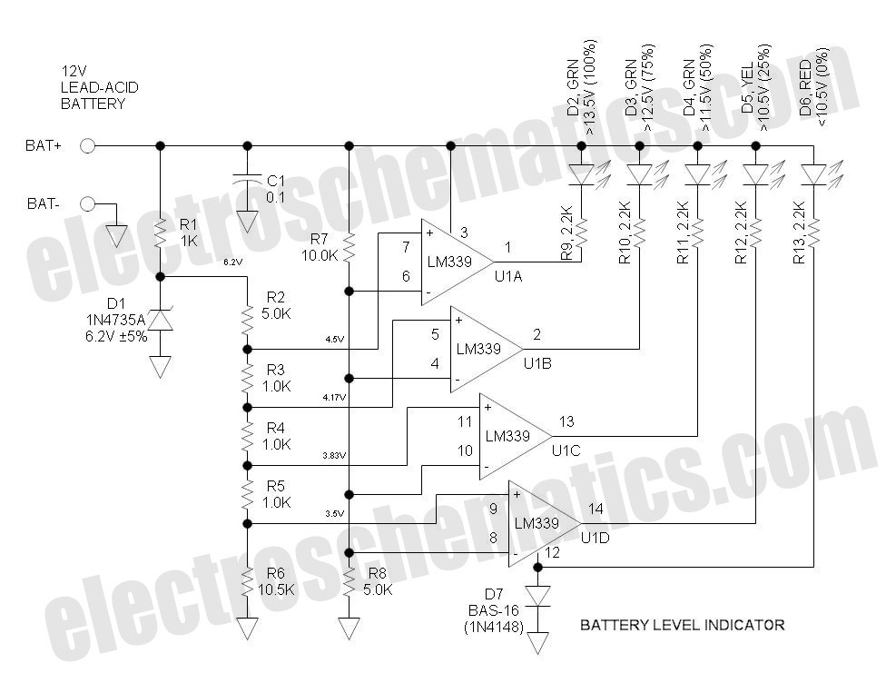
12V Battery Level Indicator Circuit
This battery level indicator features five LEDs that illuminate progressively as the voltage increases: Red indicates power connection (0%), Yellow signifies voltage greater than 10.5V (25%).
The battery level indicator circuit utilizes a series of five light-emitting diodes (LEDs) to provide...