


Extend current application circuit
#current extension
#three-terminal device
#output current
#voltage regulation
#power management
#integrated circuit
#1.5A
#current limit
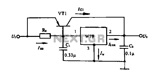
Description: Extend the current application circuit. The maximum output current of the integrated three-terminal device in production is 1.5A. If the output current exceeds 1.5A, an external power transistor can be utilized to increase the output current, as illustrated in the circuit connection.
To enhance the output current capability of the integrated three-terminal device, an external power transistor can be incorporated into the existing circuit. This configuration allows the system to handle currents greater than the device's inherent limit of 1.5A. The external transistor acts as a current amplifier, enabling the circuit to support higher loads without compromising the performance of the integrated device.
The schematic typically includes the integrated three-terminal device connected to the base of the external power transistor through a biasing resistor. This resistor is crucial for controlling the base current of the transistor, thus regulating its operation. The collector of the power transistor is connected to the load, while the emitter is grounded. A feedback mechanism may also be implemented to stabilize the output current and prevent thermal runaway, which could potentially damage the components.
In this configuration, it is essential to consider the power rating and thermal characteristics of the external transistor to ensure reliable operation. Adequate heat sinking may be required to dissipate excess heat generated during operation, especially when driving high currents. Additionally, protective components such as diodes may be included to safeguard against voltage spikes that could occur during switching events.
Overall, this approach provides a practical solution for applications requiring higher current outputs while maintaining the integrity and functionality of the existing circuit design.Extend current application circuit The current production of the maximum output current of the integrated three-terminal device is 1.5A. If the output current is greater than t he need to 1.5A, the external power transistor can be used to expand the output current method, as shown in the circuit connection.
To enhance the output current capability of the integrated three-terminal device, an external power transistor can be incorporated into the existing circuit. This configuration allows the system to handle currents greater than the device's inherent limit of 1.5A. The external transistor acts as a current amplifier, enabling the circuit to support higher loads without compromising the performance of the integrated device.
The schematic typically includes the integrated three-terminal device connected to the base of the external power transistor through a biasing resistor. This resistor is crucial for controlling the base current of the transistor, thus regulating its operation. The collector of the power transistor is connected to the load, while the emitter is grounded. A feedback mechanism may also be implemented to stabilize the output current and prevent thermal runaway, which could potentially damage the components.
In this configuration, it is essential to consider the power rating and thermal characteristics of the external transistor to ensure reliable operation. Adequate heat sinking may be required to dissipate excess heat generated during operation, especially when driving high currents. Additionally, protective components such as diodes may be included to safeguard against voltage spikes that could occur during switching events.
Overall, this approach provides a practical solution for applications requiring higher current outputs while maintaining the integrity and functionality of the existing circuit design.Extend current application circuit The current production of the maximum output current of the integrated three-terminal device is 1.5A. If the output current is greater than t he need to 1.5A, the external power transistor can be used to expand the output current method, as shown in the circuit connection.

psu
The Chameleon II Power Supply Circuits convert the raw input supply into stable voltage outputs necessary for the Chameleon interfaces. The outputs provided are +5V, +12V, and -12V.
The Chameleon II Power Supply Circuits are designed to ensure reliable operation of...
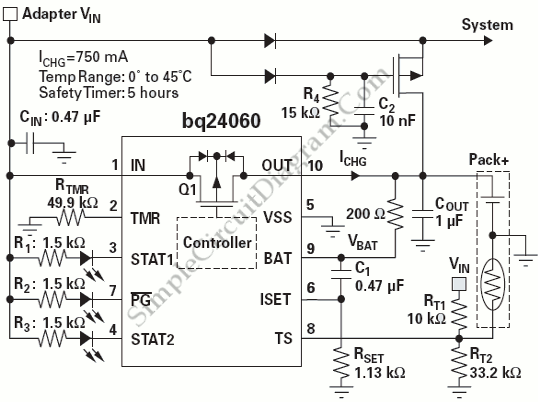
Power Path Management Battery Charger
Powering the system is required by many applications while charging the battery simultaneously. Interaction between the system and charger may result in a...
Power management in electronic systems is critical, particularly in applications that necessitate simultaneous operation and battery charging. This...

A Power Management Interface Circuit For Telecom Hot Swap With Local Dc/dc Conve
New cellular phones have incorporated high-resolution cameras that require bright illumination of the surrounding area to achieve high-quality pictures. Traditional xenon-filled photo flashes cannot be used due to the limited space available in cellular phone cameras. Instead, design engineers utilize...
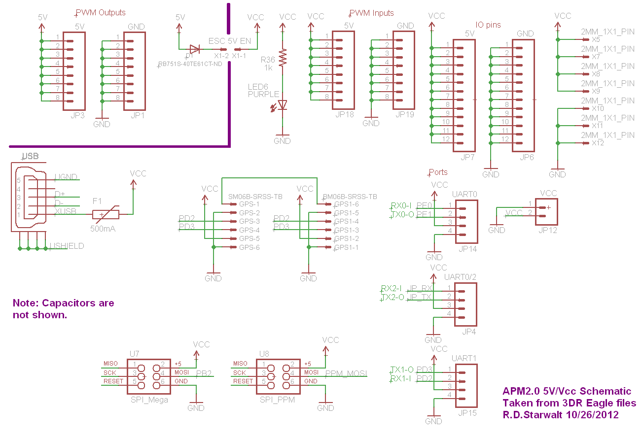
APM2.0 5V/Vcc Schematic
The PWM Output section has been separated into the upper left corner, delineated by a heavy purple line that is bridged by jumper JP1 on the APM2.0. This design choice highlights that diode D1 allows current to pass through JP1,...
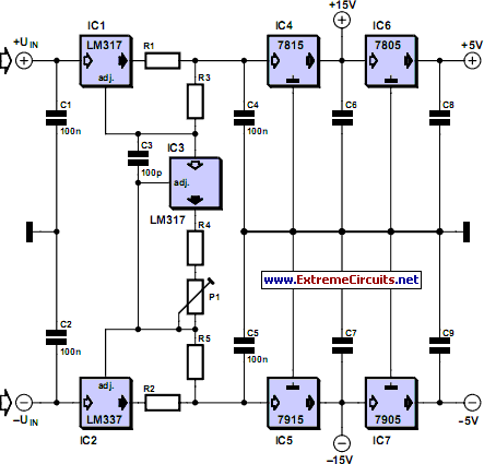
Adjustable Current Limit For Dual Power Supply
This current-limiting circuit, illustrated as part of a small bench power supply, can be utilized with any dual-rail current source. The section of the circuit to the left limits the current at the input to the dual voltage regulator (IC4...
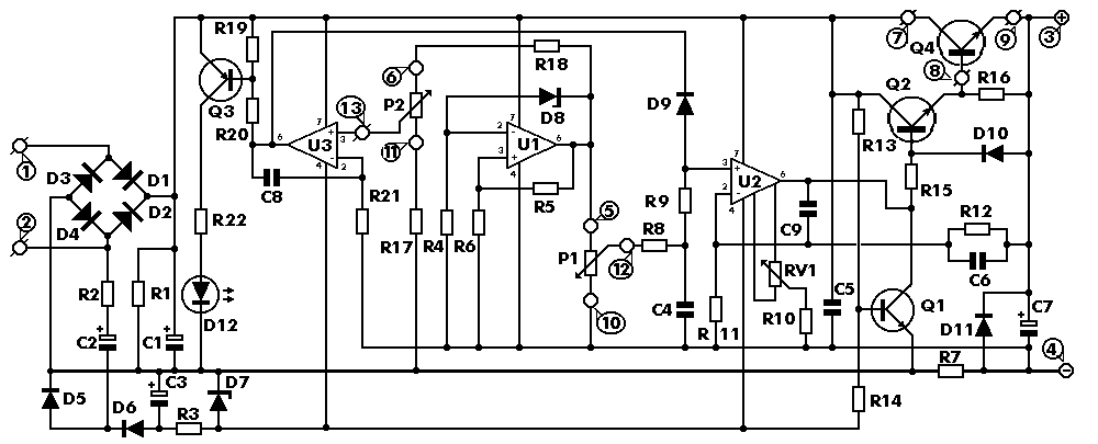
0-30 VDC Stabilized Power Supply with Current Control 0.002-3 A
The circuit begins with a step-down mains transformer featuring a secondary winding rated at 24 V/3 A, which connects across the input points at pins 1 and 2. The quality of the output supply is directly related to the transformer's...
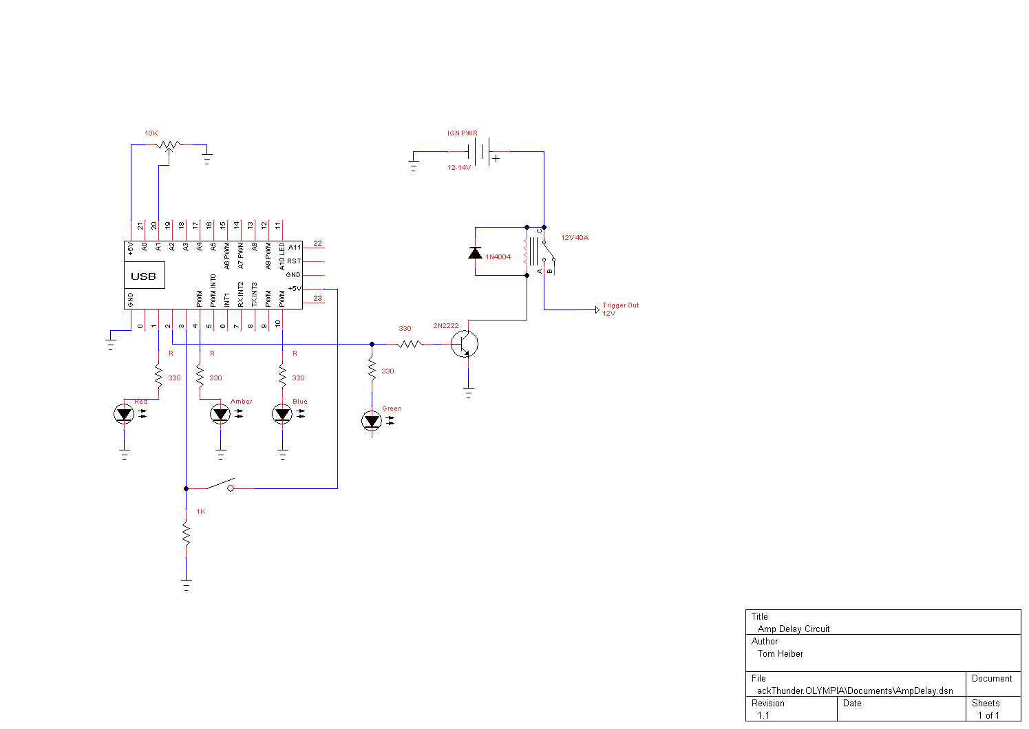
smart amp delay
This system is designed as a Windows service that detects various power events, including Suspend, Hibernate, Reboot, and Shutdown. It can send appropriate responses to a control circuit, specifically a Heartbeat or Kill signal. The trigger mechanism is also regulated...
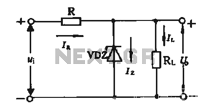
Regulator circuit silicon resistor formed
The simple voltage regulator circuit consists of a silicon regulator and a resistor. It is designed to rectify and filter DC voltage, as illustrated in the accompanying figure. The voltage regulator is connected in parallel with the load, and the...
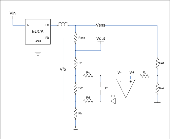
Current Limit Circuit for Voltage Regulator
This is a cost-effective circuit that incorporates precise current limiting functionality into a voltage regulator.
The circuit described is designed to enhance the performance of a voltage regulator by integrating a current limiting feature. This is particularly beneficial in applications where...