


Extended output current application
#78 series
#voltage regulator
#current extension
#power supply
#1.5A
#integrated circuit
#DC power
#electronic component
#circuit design
#current boost
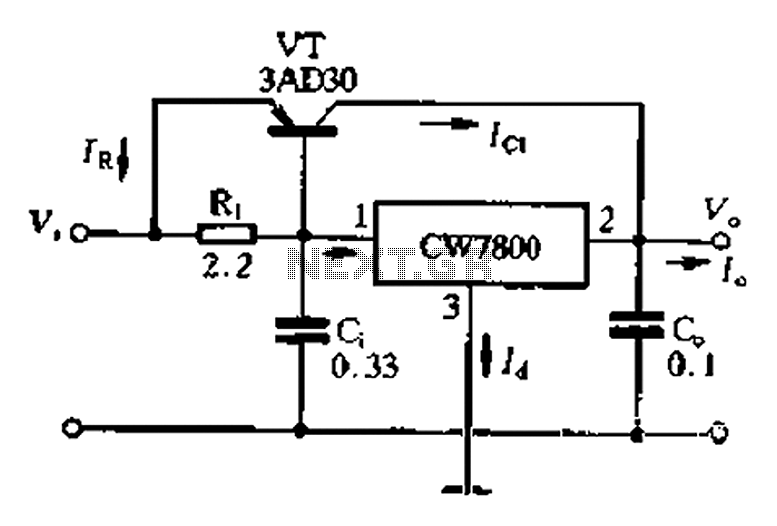
Description: The 78 Series integrated voltage regulator has a rated output current of 1.5A. For applications requiring larger output currents, the output current can be increased using the square method. This method typically involves connecting multiple regulators of the same type in parallel, ensuring that each regulator shares the load evenly. Additionally, external power sources can be utilized alongside the regulator, as illustrated in Figure 7-200, which includes the connection to a diffuser tube with PNP polarity for power management. The integration of this configuration with an NPN regulator adjustment tube forms a composite circuit. The bias current for regulation is established through a bleeder resistor, which determines the minimum output current of the regulator.
The 78 Series integrated voltage regulator is designed to provide a stable output voltage with a maximum output current of 1.5A. It is commonly used in various electronic applications where a reliable power supply is essential. The square method for extending output current involves paralleling multiple regulators, which allows for increased current capacity without exceeding the individual regulator's limits. Each regulator in the parallel configuration must be matched to ensure uniform current distribution, preventing thermal overload and ensuring stability.
The external power source can be connected to the regulator's input, enabling the system to handle higher power demands. The PNP polarity configuration is crucial for the management of power in this setup, allowing for efficient control of the output voltage. The composite circuit formed by integrating the NPN regulator adjustment tube allows for fine-tuning of the output voltage, enhancing the overall performance of the power supply.
The bias current, supplied through the bleeder resistor, plays a critical role in maintaining the regulator's performance. This resistor helps to set the minimum output current, ensuring that the regulator operates within its specified parameters even under varying load conditions. Proper selection of the bleeder resistor value is essential for achieving the desired output characteristics and ensuring reliable operation of the entire circuit.
In summary, the 78 Series voltage regulator is a versatile component that can be adapted for higher output currents through parallel configurations and external power sources, making it suitable for a wide range of applications in electronic circuit design.78 Series integrated voltage regulator rated output current of 1.5A, For larger output current, the output current can be extended using the square method. Extended output curr ent method most cylinder is the same type of integration steady pressure used in parallel, each using the same electrode connected o In addition to this external power can also be used outside of the regulator, as shown in Figure 7-200 in the connected diffuser tube PNP polarity of power management, its integration with the NPN regulator adjustment tubes composite pipe. Figure Ri is regulated bias current bleeder resistor o its big teenager decided regulator minimum output current o
The 78 Series integrated voltage regulator is designed to provide a stable output voltage with a maximum output current of 1.5A. It is commonly used in various electronic applications where a reliable power supply is essential. The square method for extending output current involves paralleling multiple regulators, which allows for increased current capacity without exceeding the individual regulator's limits. Each regulator in the parallel configuration must be matched to ensure uniform current distribution, preventing thermal overload and ensuring stability.
The external power source can be connected to the regulator's input, enabling the system to handle higher power demands. The PNP polarity configuration is crucial for the management of power in this setup, allowing for efficient control of the output voltage. The composite circuit formed by integrating the NPN regulator adjustment tube allows for fine-tuning of the output voltage, enhancing the overall performance of the power supply.
The bias current, supplied through the bleeder resistor, plays a critical role in maintaining the regulator's performance. This resistor helps to set the minimum output current, ensuring that the regulator operates within its specified parameters even under varying load conditions. Proper selection of the bleeder resistor value is essential for achieving the desired output characteristics and ensuring reliable operation of the entire circuit.
In summary, the 78 Series voltage regulator is a versatile component that can be adapted for higher output currents through parallel configurations and external power sources, making it suitable for a wide range of applications in electronic circuit design.78 Series integrated voltage regulator rated output current of 1.5A, For larger output current, the output current can be extended using the square method. Extended output curr ent method most cylinder is the same type of integration steady pressure used in parallel, each using the same electrode connected o In addition to this external power can also be used outside of the regulator, as shown in Figure 7-200 in the connected diffuser tube PNP polarity of power management, its integration with the NPN regulator adjustment tubes composite pipe. Figure Ri is regulated bias current bleeder resistor o its big teenager decided regulator minimum output current o
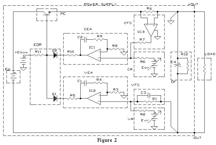
AMPLIFIER WITH FORCED EQUILIBRIUM ADAPTOR
Each power supply, whether linear or switching, operates in at least two modes: constant voltage (CV) and constant current (CC). The power supply can function in either mode, with the other serving as a protective mode for both the load...
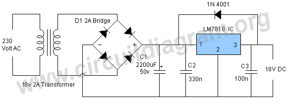
18v power supply using lm7818
This power supply operates effectively to provide a stable 18V DC output with a maximum current of 1.5A. The circuit employs an LM7818 positive voltage regulator integrated circuit (IC), which includes several built-in features such as internal current limiting, short...
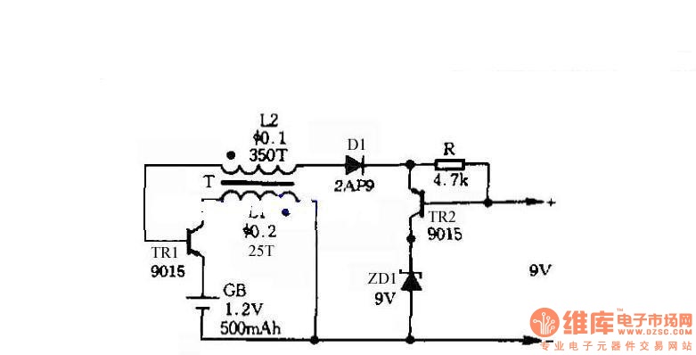
Self-control digital inverter power supply circuit diagram:1.2V rising to 9V
The circuit does not require a separate power switch or transformation to control the switches on the table. It offers advantages such as low power consumption, stability, reliability, and no impact on instrument accuracy. The transformer T in the circuit...
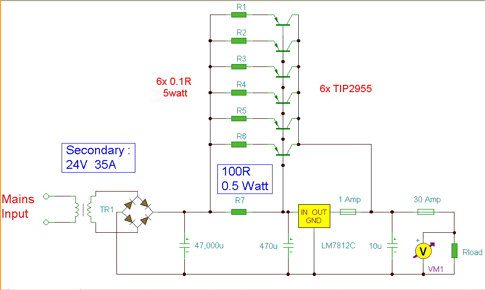
12 Volt 30 Amp PSU
Using a single 7812 IC voltage regulator and multiple outboard pass transistors, this power supply can deliver output load currents of up to 30 amps. The input transformer is likely to be the most expensive part of the entire project....
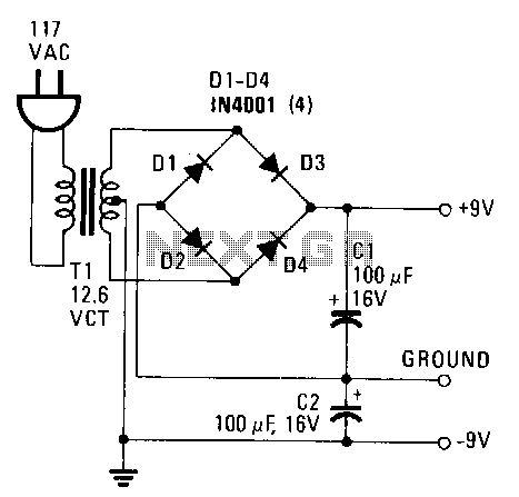
Simple-power-supply
This power supply provides both +9 V and -9 V outputs to replace two 9-V batteries. The rectifier circuit consists of two separate full-wave rectifiers, each connected to the secondary winding of the transformer. The first full-wave rectifier, made up...
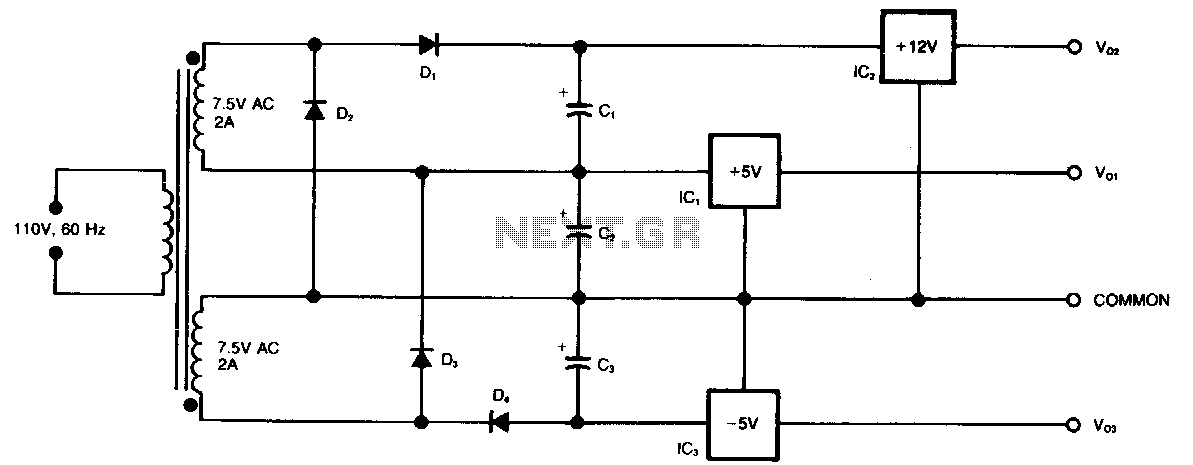
Three-rail-power-supply
This circuit generates three supply voltages using a minimal number of components. Diodes D2 and D3 perform full-wave rectification, alternately charging capacitor C2 during both halves of the AC cycle. Meanwhile, diode D1 in conjunction with capacitor C1, and diode...

voltage regulator circuit with pass
This is a simple design for a voltage regulator circuit using a pass transistor. The design is built around the LM317T. The output current of the LM317T can be increased by incorporating an additional power transistor to share a portion...

symmetric 12v to 5v converter
Symmetric 12V to 5V converter power supply. Refer to the designated page for an explanation regarding the associated circuit diagram.
The symmetric 12V to 5V converter power supply is designed to efficiently step down a 12V input voltage to a regulated...

Logic PSU With Over-Voltage Protection
A simple 5 Volt regulated power supply unit (PSU) featuring overvoltage protection. This 5 Volt regulated power supply is designed for TTL and 74LS series integrated circuits.
The 5 Volt regulated power supply unit is an essential component in electronic designs...