


Fan speed controller using LM2941
#fan speed controller
#LM2941
#voltage regulator
#DC fan
#low dropout
#12V
#power supply
#speed control
#electronic circuit
#DIY
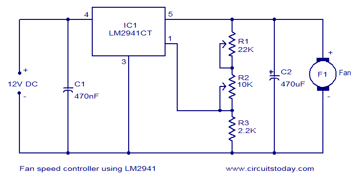
Description: Numerous electronic circuits designed for fan speed control have been documented, and this one presents an alternative method. The circuit diagram illustrates a 12V DC fan speed controller utilizing the LM2941CT integrated circuit, which is a low dropout 1A voltage regulator. This IC features a dropout voltage as low as 0.5V and offers several beneficial attributes, including reverse protection, thermal protection, and short circuit protection. The maximum output current that the IC can provide is 1A. The 12V DC supply is connected between the Vin (pin 4) and ground (pin 3) of the IC. The load, represented by the fan, is connected across the Vout (pin 5) and ground (pin 3) of the IC. A network consisting of potentiometers R1, R2, and a resistor determines the adjustment current (Iadj) of the IC. By varying the Iadj through the potentiometer R2, the output voltage of the IC can be adjusted, thereby controlling the fan speed.
The 12V DC fan speed controller circuit employs the LM2941CT voltage regulator, which is notable for its low dropout voltage, enabling it to maintain a stable output voltage even with minimal input voltage overhead. This characteristic is particularly advantageous in battery-operated applications where efficiency is critical. The IC's built-in protections, including reverse polarity, thermal shutdown, and short-circuit protection, enhance the reliability and safety of the circuit, making it suitable for various applications where fan operation needs to be controlled under varying load conditions.
The circuit's configuration allows for easy adjustment of the fan speed through the use of potentiometers. The adjustment current (Iadj) is crucial for regulating the output voltage, which directly influences the fan's operational speed. By modifying the resistance of potentiometer R2, the user can fine-tune the output voltage. This design aspect provides flexibility, allowing the user to achieve the desired airflow based on specific cooling requirements.
In practical implementation, the circuit should be laid out on a suitable PCB to minimize parasitic inductance and resistance, ensuring stable operation. Proper heat dissipation measures must be considered, especially since the LM2941CT can supply up to 1A of current. Adequate thermal management will prevent overheating and extend the lifespan of the circuit components. Additionally, the choice of the fan should align with the circuit's specifications to ensure compatibility and optimal performance.Many electronic circuits related to fan speed controlling have been published here and this one is just another approach. The circuit diagram shown here is of 12V DC fan speed controller using the IC LM2941CT which is a low drop out 1A voltage regulator.
The IC has a dropout voltage as low as 0. 5 and has also many useful features like power supply reverse protection, thermal protection, short circuit protection etc. The maximum output current the IC can source is 1A. The 12V DC supply is connected between the Vin (pin4) and ground (pin3) of the IC. The load, which is the fan, is connected across the Vout (pin5) and ground (pin3) of the IC. The network comprising of potentiometers R1, R2 and resistor determines adjust current (Iadj) of the IC. By varying the Iadj using the POT R2 we can adjust the output voltage of the IC and hence the fan speed.
The 12V DC fan speed controller circuit employs the LM2941CT voltage regulator, which is notable for its low dropout voltage, enabling it to maintain a stable output voltage even with minimal input voltage overhead. This characteristic is particularly advantageous in battery-operated applications where efficiency is critical. The IC's built-in protections, including reverse polarity, thermal shutdown, and short-circuit protection, enhance the reliability and safety of the circuit, making it suitable for various applications where fan operation needs to be controlled under varying load conditions.
The circuit's configuration allows for easy adjustment of the fan speed through the use of potentiometers. The adjustment current (Iadj) is crucial for regulating the output voltage, which directly influences the fan's operational speed. By modifying the resistance of potentiometer R2, the user can fine-tune the output voltage. This design aspect provides flexibility, allowing the user to achieve the desired airflow based on specific cooling requirements.
In practical implementation, the circuit should be laid out on a suitable PCB to minimize parasitic inductance and resistance, ensuring stable operation. Proper heat dissipation measures must be considered, especially since the LM2941CT can supply up to 1A of current. Adequate thermal management will prevent overheating and extend the lifespan of the circuit components. Additionally, the choice of the fan should align with the circuit's specifications to ensure compatibility and optimal performance.Many electronic circuits related to fan speed controlling have been published here and this one is just another approach. The circuit diagram shown here is of 12V DC fan speed controller using the IC LM2941CT which is a low drop out 1A voltage regulator.
The IC has a dropout voltage as low as 0. 5 and has also many useful features like power supply reverse protection, thermal protection, short circuit protection etc. The maximum output current the IC can source is 1A. The 12V DC supply is connected between the Vin (pin4) and ground (pin3) of the IC. The load, which is the fan, is connected across the Vout (pin5) and ground (pin3) of the IC. The network comprising of potentiometers R1, R2 and resistor determines adjust current (Iadj) of the IC. By varying the Iadj using the POT R2 we can adjust the output voltage of the IC and hence the fan speed.
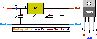
9 Volt 2 Ampere DC Power SupplyCircuit
A simple 9 Volt, 2 amp power supply utilizing a single integrated circuit (IC) regulator. This circuit is straightforward, as the regulator handles the majority of the work. The component used is the 7809 voltage regulator.
The circuit consists primarily of...

12 v nicad battery charger 200mah
12V NiCad battery charger with a 200mA/h power supply. Refer to the specified page for an explanation regarding the related circuit diagram.
The circuit for a 12V NiCad battery charger designed to supply a current of 200mA/h typically includes several key...
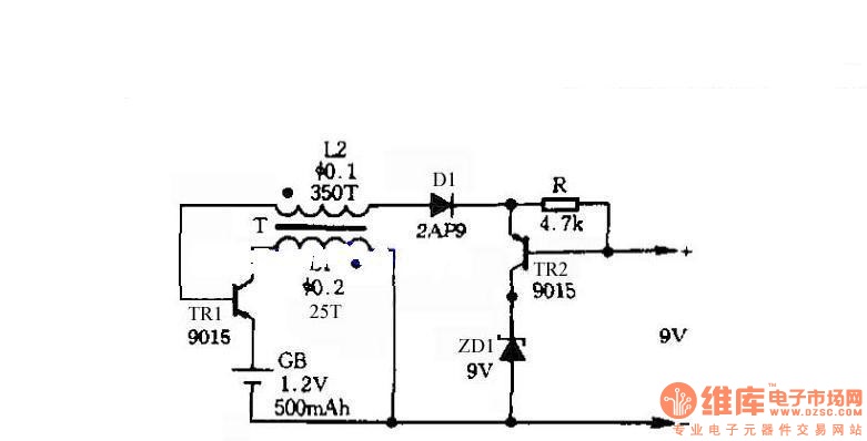
Self-control digital inverter power supply circuit diagram:1.2V rising to 9V
The circuit does not require a separate power switch or transformation to control the switches on the table. It offers advantages such as low power consumption, stability, reliability, and no impact on instrument accuracy. The transformer T in the circuit...
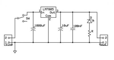
ic-7805 based 5V breadboard mini PSU circuit with explanation
A micro power supply unit (PSU) is designed to power a breadboard with a voltage output of 5 volts. It can be connected to a 9V battery, a 12V source, or any other direct current (DC) power supply ranging from...
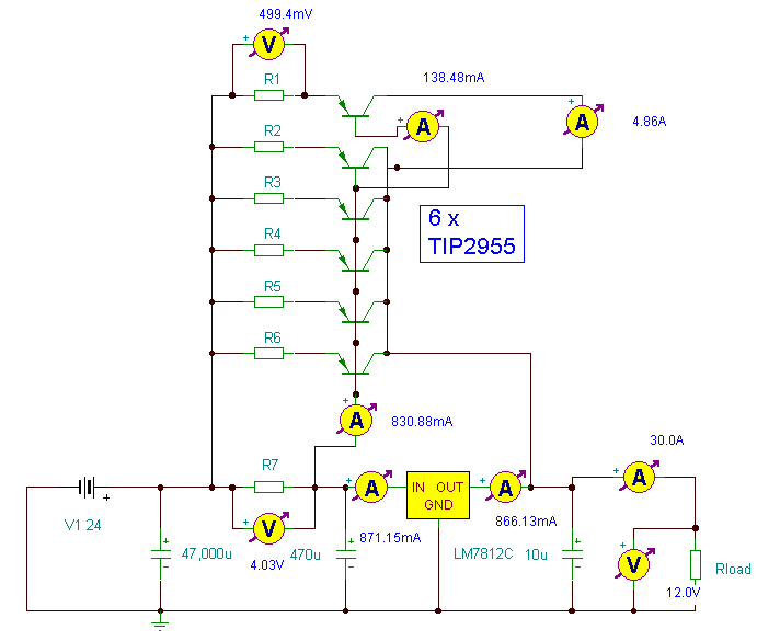
12 Volt 30 Amp Power Supply
This power supply utilizes a single 7812 integrated circuit (IC) voltage regulator in conjunction with multiple external pass transistors to provide output load currents of up to 30 amps.
The circuit design incorporates a 7812 voltage regulator, which is known for...
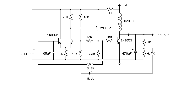
2 watt switching power supply
This compact switching power supply utilizes a Schmitt trigger oscillator to control a switching transistor, which provides current to a small inductor. When the transistor is activated, energy accumulates in the inductor, and this energy is subsequently released into the...
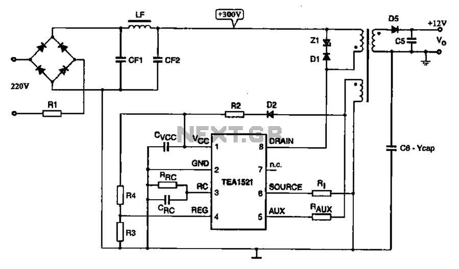
A typical DVD switching power supply circuit
A typical DVD switching power supply circuit is shown in the standby power supply circuit of digital products. It utilizes a switching power supply structure, with the oscillation switch IC EA1623 providing oscillation pulses to the transformer. The secondary output...
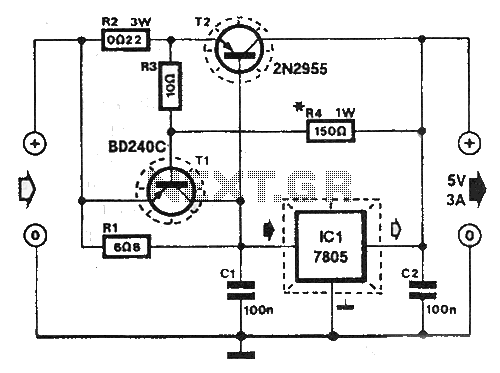
Shortcircuit protected voltage regulator
At this voltage regulator prototype the maximum current, with output shortcircuited it was only 0.5 A, so no overheating occurred. In this DC voltage regulator circuit, T1 is for current limitation. As soon as the voltage on the R2 +...
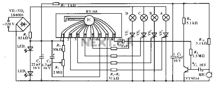
Lighting controller circuit
The circuit operates with a controller that includes a power supply circuit, a control circuit, and an audio amplifier, which are three distinct components. The power circuit comprises diodes VD1 to VD4, resistor R1, capacitor C1, LED1, LED2, and additional...