


LM317 Regulator Circuit
#LM317
#voltage regulator
#heatsink
#zener diode
#LED indicator
#DC power
#over-voltage protection
#1 amp
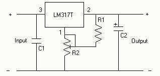
Description: The voltage regulator is an LM317T, and should accept up to about 14 volts without problems. It can handle up to 1 amp, but you WILL need a heatsink on the voltage regulator. I also added DC power jacks for input and output on my voltage regulator, a green power LED, and a red over-voltage LED. The over voltage LED uses a zener diode to switch on the LED at a certain preset voltage, this can be varied depending on the voltage of the zener diode, I used a 6.2v zener diode. More: If you plan to vary the voltage for the different items you power, don`t bother adding this feature. If you only plan to use items that run on one voltage, this is a very useful feature and will save plugging in and damaging your valuable (or not so.
The LM317T voltage regulator is a versatile and widely used component in electronic circuits, capable of providing a stable output voltage with a maximum output current of 1 amp. It operates with an input voltage range typically up to 14 volts, making it suitable for various applications, including powering low-voltage devices.
In the described circuit, the LM317T is configured with appropriate resistors to set the desired output voltage. The output voltage can be adjusted by changing the resistor values connected to the adjustment pin of the LM317T. This allows for flexibility in powering devices that require different voltage levels. However, if the circuit is intended for devices that operate at a single voltage, the adjustable feature may be unnecessary.
To ensure reliable operation, a heatsink is mandatory for the LM317T, as it dissipates heat generated during voltage regulation, especially when the input voltage is significantly higher than the output voltage. The heatsink should be appropriately sized to maintain the regulator's temperature within safe limits during operation.
The circuit includes DC power jacks for both input and output connections, facilitating easy integration into various setups. The incorporation of a green power LED serves as a power indicator, illuminating when the circuit is powered on. Additionally, a red over-voltage LED is included to provide a visual alert if the output voltage exceeds a predetermined threshold. This LED is controlled by a zener diode, which is selected based on the specific voltage level required for activation; in this case, a 6.2V zener diode is utilized.
The zener diode's breakdown voltage can be adjusted by selecting a different zener, allowing for customization of the over-voltage protection feature. This is particularly beneficial for safeguarding sensitive electronic components from damage due to excessive voltage.
Overall, this voltage regulator circuit is designed for practicality and efficiency, providing essential features for voltage regulation while ensuring user safety through visual indicators and over-voltage protection.The voltage regulator is an LM317T, and should accept up to about 14 volts without problems. It can handle up to 1 amp, but you WILL need a heatsink on the voltage regulator. I also added DC power jacks for input and output on my voltage regulator, a green power LED, and a red over-voltage LED. The over voltage LED uses a zener diode to switch on the LED at a certain preset voltage, this can be varied depending on the voltage of the zener diode, I used a 6.2v zener diode.
If you plan to vary the voltage for the different items you power, don`t bother adding this feature. If you only plan to use items that run on one voltage, this is a very useful feature and will save plugging in and damaging your valuable (or not so
The LM317T voltage regulator is a versatile and widely used component in electronic circuits, capable of providing a stable output voltage with a maximum output current of 1 amp. It operates with an input voltage range typically up to 14 volts, making it suitable for various applications, including powering low-voltage devices.
In the described circuit, the LM317T is configured with appropriate resistors to set the desired output voltage. The output voltage can be adjusted by changing the resistor values connected to the adjustment pin of the LM317T. This allows for flexibility in powering devices that require different voltage levels. However, if the circuit is intended for devices that operate at a single voltage, the adjustable feature may be unnecessary.
To ensure reliable operation, a heatsink is mandatory for the LM317T, as it dissipates heat generated during voltage regulation, especially when the input voltage is significantly higher than the output voltage. The heatsink should be appropriately sized to maintain the regulator's temperature within safe limits during operation.
The circuit includes DC power jacks for both input and output connections, facilitating easy integration into various setups. The incorporation of a green power LED serves as a power indicator, illuminating when the circuit is powered on. Additionally, a red over-voltage LED is included to provide a visual alert if the output voltage exceeds a predetermined threshold. This LED is controlled by a zener diode, which is selected based on the specific voltage level required for activation; in this case, a 6.2V zener diode is utilized.
The zener diode's breakdown voltage can be adjusted by selecting a different zener, allowing for customization of the over-voltage protection feature. This is particularly beneficial for safeguarding sensitive electronic components from damage due to excessive voltage.
Overall, this voltage regulator circuit is designed for practicality and efficiency, providing essential features for voltage regulation while ensuring user safety through visual indicators and over-voltage protection.The voltage regulator is an LM317T, and should accept up to about 14 volts without problems. It can handle up to 1 amp, but you WILL need a heatsink on the voltage regulator. I also added DC power jacks for input and output on my voltage regulator, a green power LED, and a red over-voltage LED. The over voltage LED uses a zener diode to switch on the LED at a certain preset voltage, this can be varied depending on the voltage of the zener diode, I used a 6.2v zener diode.
If you plan to vary the voltage for the different items you power, don`t bother adding this feature. If you only plan to use items that run on one voltage, this is a very useful feature and will save plugging in and damaging your valuable (or not so
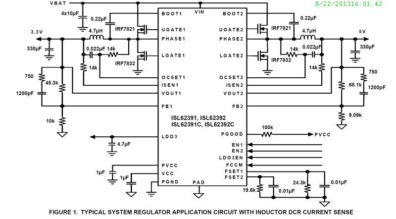
ISL62391
The ISL62391 controller generates supply voltage for battery-powered systems. It includes two pulse-width modulation (PWM) controllers, adjustable from 0.6V to 5.5V, and a linear regulator (LDO3) that generates a fixed 3.3V and can deliver up to 100mA. The ISL62391 includes...
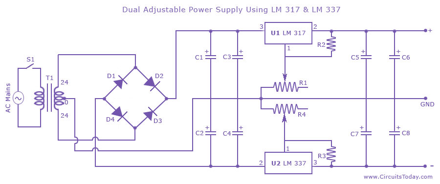
Dual Adjustable/Variable Power Supply Circuit Using LM 317 & LM337
Dual adjustable power supply circuit with a diagram using IC LM317 and LM337. This variable power supply circuit has a range of 1.2 volts to 30 volts.
The dual adjustable power supply circuit utilizes the LM317 and LM337 voltage regulators to...
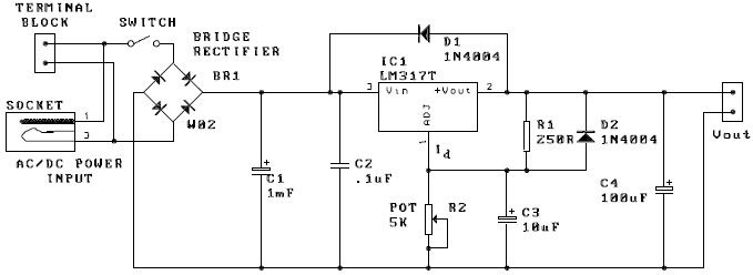
lm317 adjustable power supply electronic project
A potentiometer, designated as R2, can be utilized to adjust the desired output voltage. The kit is capable of accepting either AC or DC input through a socket or terminal block. It is advisable to incorporate protection diodes when external...
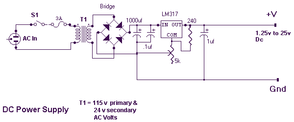
Variable DC Power Supply
This power supply is based on the LM317 Variable Regulator. The input of the regulator needs to be around 28 Volts DC and it will output a DC voltage from 1.25vdc to 25 vdc. To adjust the output voltage simply...
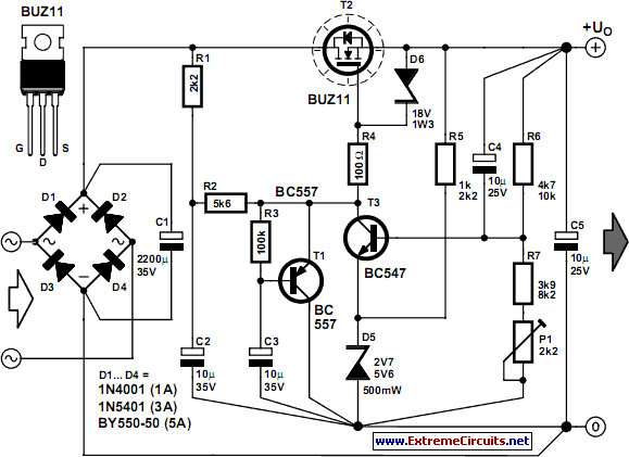
Stable Filament Power Supply Circuit
The circuit diagram illustrates a voltage regulator designed from discrete components to meet specific voltage requirements. It provides two sets of component values for output voltages of 6.3 V (upper) and 12.6 V (lower). The components used include BC547 and...
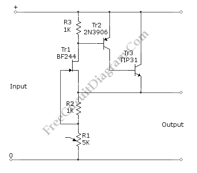
5V FET Voltage Regulator
This voltage regulator circuit provides a stable 5V output from unregulated inputs that are greater than 5V. The output voltage stability is satisfactory, with minimal variations.
The voltage regulator circuit utilizes a linear voltage regulator, such as the LM7805, which is...
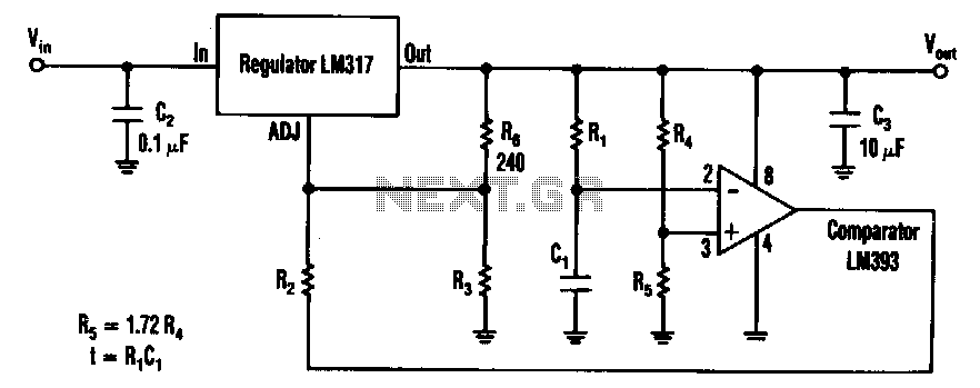
Start-and-run-motor-circuit
The timed two-voltage circuit can start and run a small DC motor or solenoid. The input voltage to the LM317 three-terminal regulator ranges from 5 to 40 V, and the output voltage can range from 2 to 36 V. With...
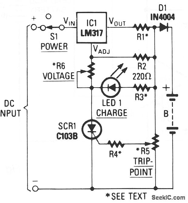
UNIVERSAL BATTERY CHARGER
When power is applied to the circuit, SCR1 remains off, resulting in no bias-current path to ground; consequently, the LM317 operates as a current regulator. The LM317 is connected to the battery through steering diode D1, limiting resistor R1, and...
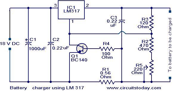
Battery charger circuit using LM317
This is a simple yet effective battery charger circuit utilizing the LM317 integrated circuit (IC). The circuit is designed for charging 12V lead-acid batteries and can be easily assembled on a general-purpose printed circuit board (PCB). The core component of...