


Plus resistive and capacitive silicon tube regulator phase trigger circuit
#phase trigger
#silicon tube
#resistive
#capacitive
#linearity
#control accuracy
#low voltage
#electroplating
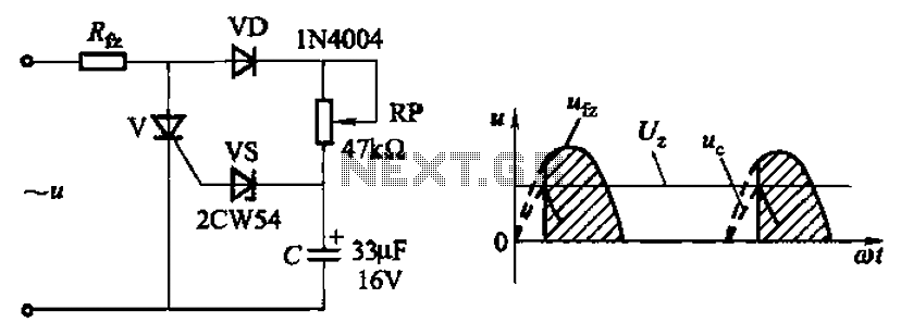
Description: Circuit characteristics: A simple phase shift range of 180 degrees; exhibits good linearity and control accuracy compared to the first two options, making it suitable for low voltage applications, particularly in less demanding electroplating and electrolysis power supplies.
The described circuit features a phase shift that can be adjusted up to 180 degrees, which is essential for various applications in signal processing and control systems. The good linearity and control accuracy of this circuit allow for precise adjustments, making it ideal for scenarios where signal integrity is crucial. This characteristic is particularly beneficial in low voltage environments, where maintaining signal quality can be challenging.
In electroplating and electrolysis power supplies, the ability to control the phase shift effectively can enhance the efficiency of the process. For instance, in electroplating, controlling the phase can influence the deposition rate and quality of the plated material. A circuit designed with these characteristics can provide stable and reliable performance, ensuring that the electrochemical processes operate within optimal parameters.
The implementation of such a circuit might involve components like operational amplifiers, resistors, and capacitors configured to achieve the desired phase shift. Additionally, feedback mechanisms can be integrated to maintain control accuracy over varying load conditions. The overall design should consider thermal management and component ratings to ensure longevity and reliability in practical applications. Circuit characteristics: O simple phase shift range 180. ; good linearity, control accuracy than the first two, and is suitable for low voltage, but less demanding electroplati ng, electrolysis power supplies.
The described circuit features a phase shift that can be adjusted up to 180 degrees, which is essential for various applications in signal processing and control systems. The good linearity and control accuracy of this circuit allow for precise adjustments, making it ideal for scenarios where signal integrity is crucial. This characteristic is particularly beneficial in low voltage environments, where maintaining signal quality can be challenging.
In electroplating and electrolysis power supplies, the ability to control the phase shift effectively can enhance the efficiency of the process. For instance, in electroplating, controlling the phase can influence the deposition rate and quality of the plated material. A circuit designed with these characteristics can provide stable and reliable performance, ensuring that the electrochemical processes operate within optimal parameters.
The implementation of such a circuit might involve components like operational amplifiers, resistors, and capacitors configured to achieve the desired phase shift. Additionally, feedback mechanisms can be integrated to maintain control accuracy over varying load conditions. The overall design should consider thermal management and component ratings to ensure longevity and reliability in practical applications. Circuit characteristics: O simple phase shift range 180. ; good linearity, control accuracy than the first two, and is suitable for low voltage, but less demanding electroplati ng, electrolysis power supplies.
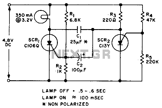
Low voltage flasher
Applying voltage to the circuit triggers SCR1. With SCR1 on, the voltage on the anode of SCR2 rises until SCR2 triggers to commutate SCR1. The voltage on the gate of SCR1 will swing negative at this time, and only after...
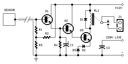
Capacitive Sensors
For proper operation, the circuit ground must be connected through a small-value, high-voltage-rated capacitor to one side of the mains supply socket. The "Live" side is the right one. This circuit is designed to animate shop windows using a capacitive...
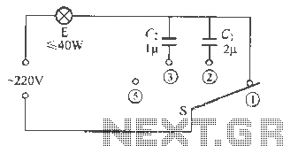
Capacitive Dimmer switch circuit
The capacitive dimmer switch circuit is illustrated in Figure 9. It operates based on the principle of capacitive reactance with alternating current. When the switch is in the position shown, the normal light bulb operates at maximum brightness. When the...
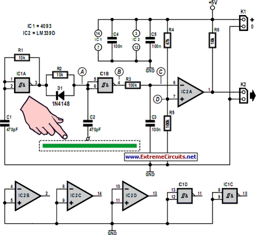
Simple Capacitive Touch Sensor
Capacitive touch sensors operate based on the electrical capacitance of the human body. When a finger approaches the sensor, it establishes a capacitance to Earth ranging from 30 to 100 pF. This phenomenon can be utilized for proximity detection and...
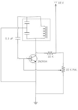
Simple low voltage Oscillator circuit
The frequency remains stable as the voltage decreases. It is referred to as the "backwards JT" because it operates optimally with a bifilar coil and a single transistor. With a modification to the circuit, it is possible to deplete a...
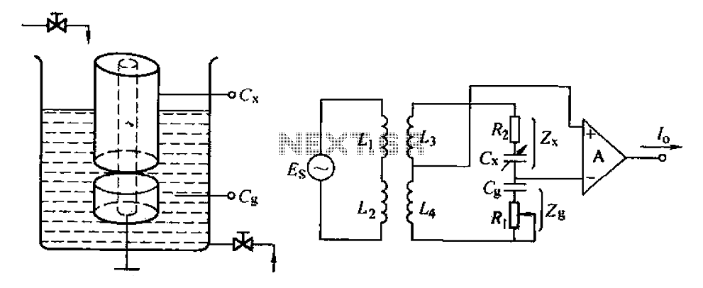
Capacitive level measuring circuit
The capacitance change in a capacitive sensor is directly converted into electrical parameters, which are then unified for signal transmission, processing, and display. These electrical parameters can be categorized into resistive, capacitive, and inductive types. This explanation focuses on capacitive...
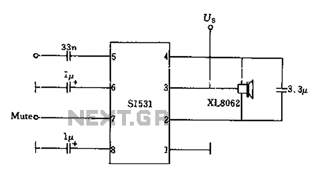
The battery voltage is low frequency amplifying circuit diagram 1v
The battery voltage is 1V for a low-frequency amplifying circuit, which can operate with a power supply voltage ranging from 1V to 1.7V, making it suitable for use with small batteries. The circuit provides an output power of 80mW with...
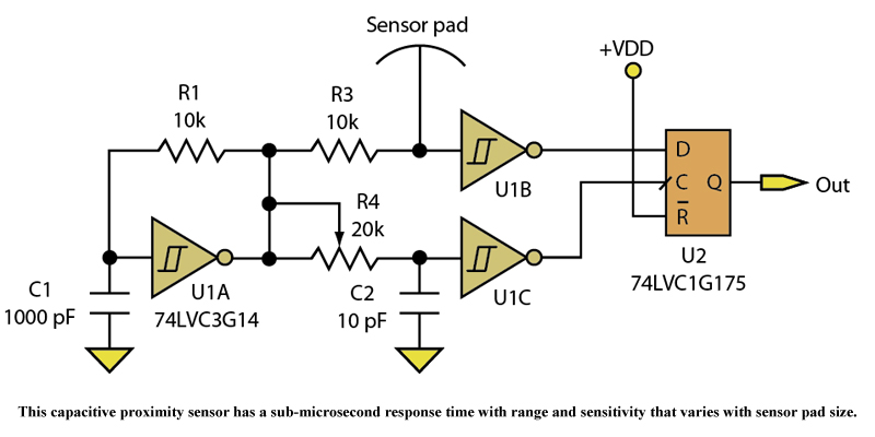
Capacitive Proximity Sensor Provides Accuracy And Speed
Three devices in a quad Schmitt Trigger and a Flip-Flop create a simple yet sensitive proximity sensor.
The described circuit utilizes three devices from a quad Schmitt Trigger configuration alongside a Flip-Flop to construct a proximity sensor. The Schmitt Trigger is...
Capacitive Dimmer switch circuit
The capacitive dimmer switch circuit is illustrated in Figure 9. It operates based on the principle of capacitive reactance with alternating current. When the switch is in the position shown, the normal light bulb operates at maximum brightness. When the...