


PMOS FET Following The Output for Soft-Start Mechanism
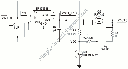
Description: A PMOS FET switch regulator output is utilized in series with the regulator's load, as illustrated in the accompanying diagram. This represents a straightforward approach to circuit design.
The described configuration employs a PMOS FET as a switching element in a linear regulator circuit. In this setup, the PMOS FET is positioned in series with the load, allowing for efficient control of the output voltage and current delivered to the load. The PMOS FET operates by switching on and off based on the control signal, which modulates the power supplied to the load according to the desired output characteristics.
In this arrangement, the gate of the PMOS FET is driven by a control voltage that determines whether the FET is in the on-state or off-state. When a positive voltage is applied to the gate relative to the source, the PMOS FET turns off, interrupting the flow of current to the load. Conversely, when the gate voltage is pulled low, the FET turns on, allowing current to flow through to the load.
The simplicity of this design lies in its minimal component count and straightforward operation. It is particularly advantageous in applications where low-power switching is required, as it can efficiently handle varying load conditions while maintaining a stable output voltage. Additionally, the use of a PMOS FET allows for high-side switching, which is beneficial in certain circuit configurations where the load needs to be connected to the positive supply rail.
In summary, the PMOS FET switch regulator configuration offers an effective and uncomplicated method for regulating output voltage in electronic circuits, making it suitable for a wide range of applications in power management systems.Using the following PMOS FET switch regulator output, in series with the regulator`s load as shown in the picture below is the most simple method. Switch..
The described configuration employs a PMOS FET as a switching element in a linear regulator circuit. In this setup, the PMOS FET is positioned in series with the load, allowing for efficient control of the output voltage and current delivered to the load. The PMOS FET operates by switching on and off based on the control signal, which modulates the power supplied to the load according to the desired output characteristics.
In this arrangement, the gate of the PMOS FET is driven by a control voltage that determines whether the FET is in the on-state or off-state. When a positive voltage is applied to the gate relative to the source, the PMOS FET turns off, interrupting the flow of current to the load. Conversely, when the gate voltage is pulled low, the FET turns on, allowing current to flow through to the load.
The simplicity of this design lies in its minimal component count and straightforward operation. It is particularly advantageous in applications where low-power switching is required, as it can efficiently handle varying load conditions while maintaining a stable output voltage. Additionally, the use of a PMOS FET allows for high-side switching, which is beneficial in certain circuit configurations where the load needs to be connected to the positive supply rail.
In summary, the PMOS FET switch regulator configuration offers an effective and uncomplicated method for regulating output voltage in electronic circuits, making it suitable for a wide range of applications in power management systems.Using the following PMOS FET switch regulator output, in series with the regulator`s load as shown in the picture below is the most simple method. Switch..
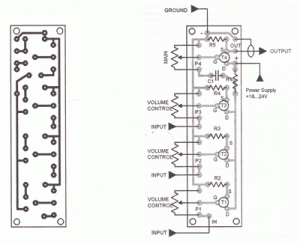
FET audio mixer circuit
This FET audio mixer demonstrates the versatility of FETs. Originally designed for high-frequency applications, FETs can also effectively handle audio frequencies, showcasing exceptional performance in this domain. The circuit can accommodate an unlimited number of inputs, provided that the resistance...
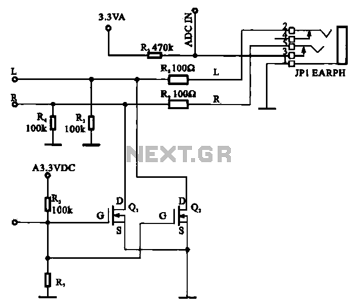
FET used as a silencer tube headphone circuit
A field-effect transistor (FET) is utilized in a headphone circuit designed to function as a silencer tube. The circuit integrates L from the digital signal processing unit and R from the audio signal into the headphone jack's mute control circuit....
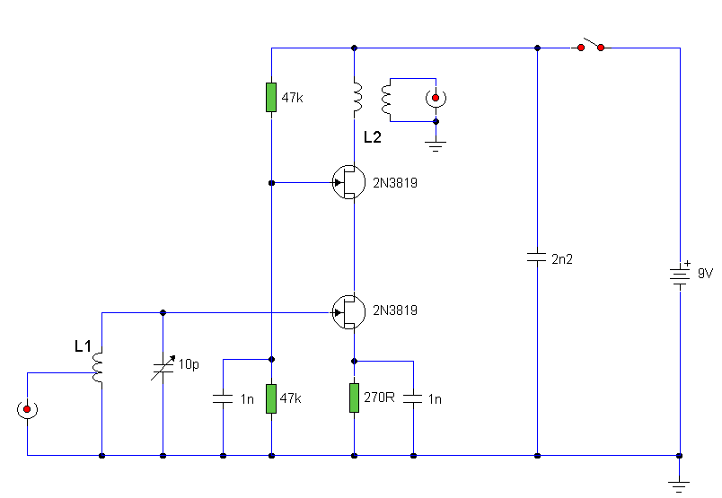
Band 2 Preamplifier
The circuit utilizes two 2N3819 FETs arranged in a cascode configuration. The lower FET functions in common source mode, while the upper FET operates in common gate mode, achieving full high-frequency gain. The lower FET is tunable, enabling peak tuning...
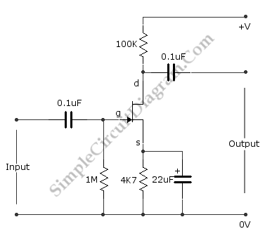
Basic FET Amplifier
This is the FET amplifier circuit, which utilizes an FET transistor. The gate of the FET must be negative relative to the source to achieve proper biasing. The voltage across the source resistor is generated by the drain current flowing...
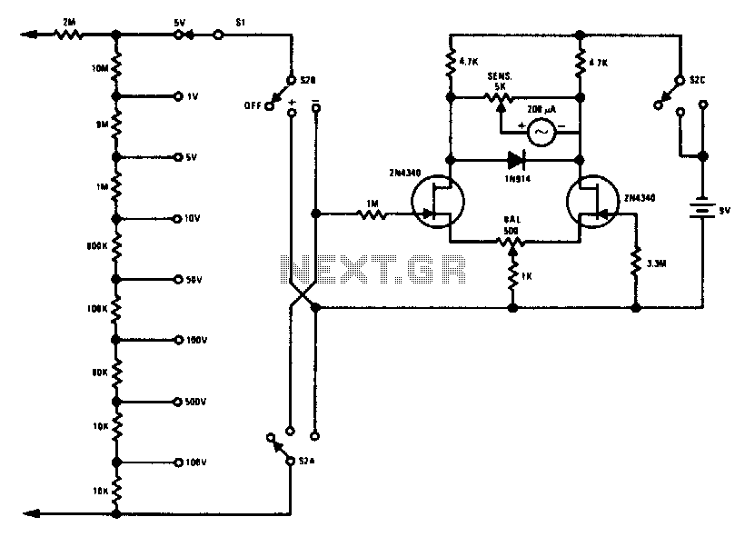
Fet voltmeter
This FETVM replaces the function of the VTVM while eliminating the need for a traditional line cord. Additionally, it offers significantly improved drift rates compared to vacuum tube circuits, enabling a 0-volt full-scale range that is generally impractical with most...

A Power Management Interface Circuit For Telecom Hot Swap With Local Dc/dc Conve
New cellular phones have incorporated high-resolution cameras that require bright illumination of the surrounding area to achieve high-quality pictures. Traditional xenon-filled photo flashes cannot be used due to the limited space available in cellular phone cameras. Instead, design engineers utilize...
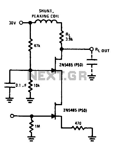
Fet cascode video amplifier
The FET cascode video amplifier exhibits very low input loading and minimizes feedback to nearly zero. The 2N5485 transistor is utilized due to its low capacitance and high transconductance (YfS). Additionally, the bandwidth of this amplifier is constrained by the...
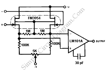
FET Op Amp
The FM3954 monolithic dual provides an ideal low-offset and low-drift buffer function for the LM101A operational amplifier. It operates effectively over its bias current range.
The FM3954 is a dual operational amplifier designed to serve as a buffer for the LM101A,...
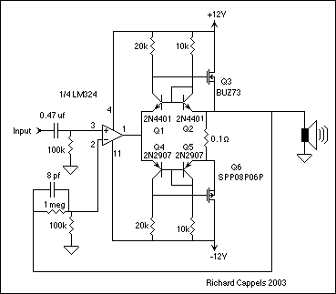
Fet Buffer for amplifiers
The EDFET drives like a FET, but with the bias stability of bipolar. Amps of output current can be controlled by milliamps of input current. The current gain is a design choice dictated by bandwidth. Two of things you have...